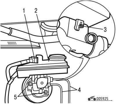
Pic. 9.25. Removing the brake master cylinder: 1 - pin connector; 2 - supply tank; 3 - cotter pin; 4 - brake pipes; 5 - nuts
- disconnect pin 1 (pic. 9.25) brake fluid level sensor;
- unscrew the cap of the supply tank 2;
- pump out the brake fluid from the supply tank with a syringe;
- remove the cotter pin 3 fastening the tank;
- remove the supply tank 2 from the main brake cylinder;
- disconnect the brake pipes 4 from the main brake cylinder;
- plug the openings of the master brake cylinder and brake pipes with plugs;
- unscrew the nuts 5 securing the master cylinder to the vacuum brake booster and remove it.
Install the master brake cylinder in the following order:

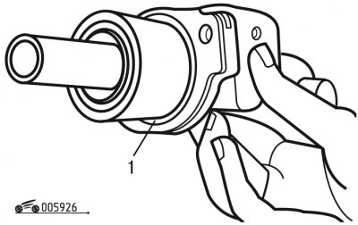
Pic. 9.26. O-ring replacement: 1 - sealing ring
- replace O-ring 1 (pic. 9.26) to a new one;

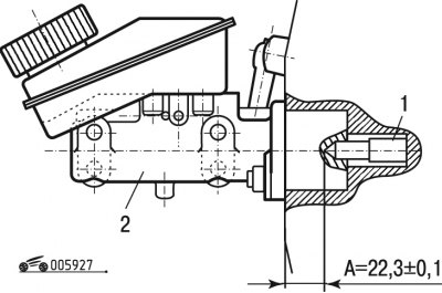
Pic. 9.27. Installation of the master brake cylinder: 1 - a rod of a vacuum brake booster; 2 - main brake cylinder; A = (22, 3±0,1) mm
- before installation, check whether the vacuum booster rod moves freely. Check that distance A (pic. 9.27) between the head of the pusher rod of the vacuum booster and the mating surface of the master brake cylinder was (22,3±0,1) mm. Otherwise, check the condition of the brake pedal.
- install the main brake cylinder on the studs and tighten the nuts 5 (see fig. 9.25) torque 20 Nm;
- carry out subsequent installation in the reverse order of removal;
- bleed the air from the hydraulic brake system.
