- loosen the wheel bolts;
- brake the car with a parking brake;
- raise the front of the vehicle and place it securely on stands;
- remove the wheel;
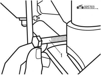
Pic. 7.3. Unscrewing the shock absorber mounting bolt: 1 - bolt
- unscrew bolt 1 (pic. 7.3) lower shock absorber mount;
- disconnect the anti-roll bar link;
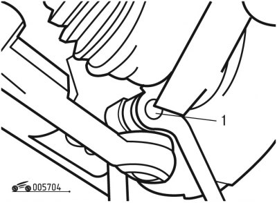
Pic. 7.4. Lower ball joint mount: 1 - nut
- unscrew nut 1 (pic. 7.4) lower ball joint mounting bolt;
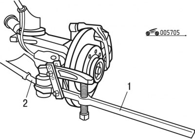
Pic. 7.5. Pressing out the ball joint pin: 1 - fixture; 2 - tie rod end
- disconnect tip 2 (pic. 7.5) tie rod from the steering knuckle by unscrewing the ball stud nut and pressing it out with a tool;
- lower the suspension arm;
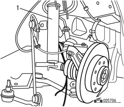
Pic. 7.6. Removing the shock absorber from the steering knuckle: 1 - shock absorber
- disconnect shock absorber body 1 (pic. 7.6) from the steering knuckle;
- tie the steering knuckle to the subframe with wire to prevent significant movement of the wheel drive shaft;
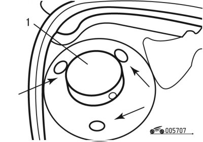
Pic. 7.7. Upper strut mount: 1 - bolt
- unscrew bolts 1 (pic. 7.7) upper shock absorber mount;
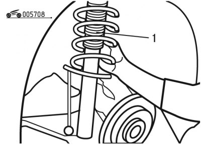
Pic. 7.8. Removing the shock absorber: 1 - shock absorber
- remove shock absorber 1 (pic. 7.8).
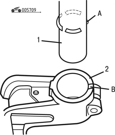
Pic. 7.9. Shock absorber installation: A - ledge; B - slot; 1 - shock absorber; 2 - steering knuckle
Installation of a shock-absorber rack is carried out in sequence, return to removal. When installing shock absorber 1 (pic. 7.9) in the steering knuckle 2, it is necessary that the protrusion A is aligned with the slot B.
