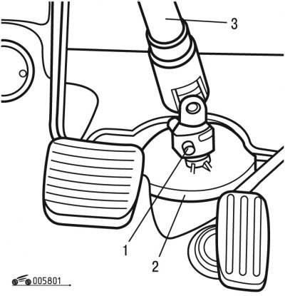
Pic. 8.1. Disconnecting the propeller shaft steering: 1 - bolt; 2 - gasket; 3 - steering wheel shaft
- unscrew bolt 1 (see fig. 8.1);
- turn off the integrated system of airbags and seat belts, observing safety precautions;
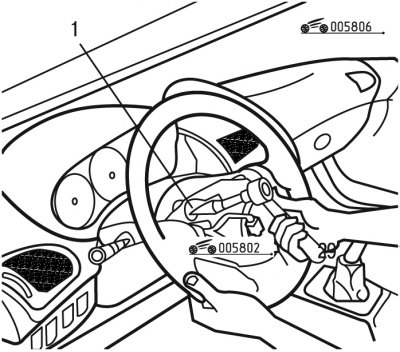
Pic. 8.6. Steering wheel mount: 1 - bolt
- Loosen bolts 1 a few turns (pic. 8.6);
- remove the steering wheel from the splines of the shaft;
- set the wheels to the straight ahead position;
- put alignment marks on the steering wheel and shaft in order to put it in the same place when reinstalling;
- unscrew bolt 1 and remove the steering wheel;
Attention! Remove the steering wheel with extreme care so as not to damage the wire harness connector.
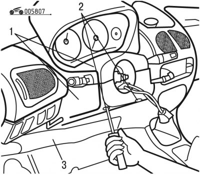
Pic. 8.7. Cover fastening: 1, 3 - casings; 2 - screws
- remove fastener 2 (pic. 8.7), then remove facing casings 1 and 3;
- disconnect and set aside the slip ring connectors;
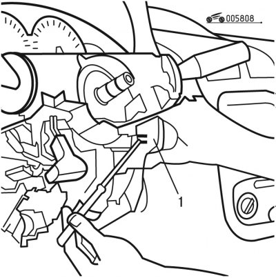
Pic. 8.8. Position of the analog module: 1 - analog module
- use a screwdriver to remove the clips and pull out the analog module 1 (pic. 8.8), releasing it from the anti-theft steering lock, and leave it in a hanging position;
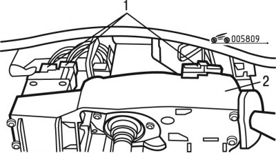
Pic. 8.9. Steering column switch connectors: 1 - contact connectors; 2 - bracket for the block of steering column switches
- disconnect connectors 1 (pic. 8.9) from bracket 2 steering column switches 2;
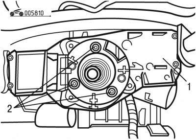
Pic. 8.10. Fastening the bracket for the steering column switch block: 1 - bracket for the block of steering column switches; 2 - bolts
- unscrew bolts 2 (pic. 8.10) fastening of an arm 1 of understeering switches 1;
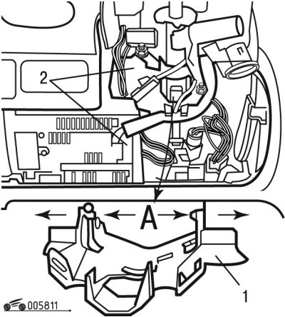
Pic. 8.11. Contact connectors: 1 - casing; 2, 3 - pin connectors; A - the lower part of the casing
- disconnect pins 2 and 3 (pic. 8.11);
- release the wiring harnesses from the casing 1;
- remove the cardan shaft by removing the protective lock;
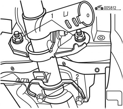
Pic. 8.12. Steering column mount: 1 - nuts; 2 - bolts
- unscrew nuts 1 (pic. 8.12) and bolts 2;
- remove the steering column.
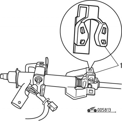
Pic. 8.13. Removing the protective brace: 1 - spacer
Install the steering column in the reverse order of removal, while doing the following:
Attention! Steering columns are delivered in spare parts together with a spacer 1 (pic. 8.13), which protects the cardan joint from damage during transportation. After installing the steering column, remove the spacer.
- tighten but do not tighten nuts 1 (see fig. 8.12) and bolts 2;
- unlock the adjustment mechanism;
- tighten nuts 1 to 40 Nm;
- lock the adjustment mechanism;
- tighten bolts 2 to 40 Nm;
- install and adjust the slip ring;
- connect a single system of airbags and seat belts;
- check the operation of the airbag warning device;
- check the normal operation of electrical appliances;
- initialize all computers.
