This mode allows:
- reduce reaction time;
- reduce fuel consumption;
- reduce harmful emissions;
- ensure compliance with EURO4 emission limits.

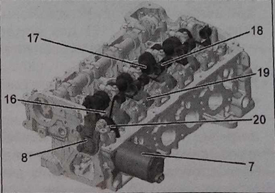
Components of the variable valve lift phase system:
7 - variable valve lift electric drive;
8 - valve position sensor;
16 - intermediate lever;
17 - intake camshaft;
18 - return spring;
19 - camshaft;
20 - gear wheel.
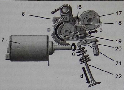
Variable intake valve lift by electric motor (7), driving the camshaft (19) with a pair of worms (20). The camshaft acts on the intermediate lever (16), located between the rocker (21) and intake camshaft (17).

Scheme of changing the phases of lifting the intake valves:
7 - electric motor for opening valves;
8 - valve position sensor;
16 - intermediate lever;
17 - intake camshaft;
18 - return spring (intermediate lever);
19 - camshaft;
20 - gear;
21 - rocker;
22 - valve;
a - shaft rotation (valve opening motor);
b - shaft rotation;
c - movement of the intermediate lever;
d - variable valve lift.
The intake camshaft acts on the valve (22) through the intermediate lever and rocker, the position of the intermediate lever determines the intake valve lift, which varies from 0.3 to 9.5 mm.
The engine-ECU controls the valve lift motor based on the following information:
- from the accelerator pedal position sensor;
- from the intake and exhaust position sensors of the engine support cylinder;
- about the position of the intake valves.
