Note. The system interface block is the same for petrol and diesel engines.
The motor junction box protects and distributes voltage for various functions using relays, fuses and circuit breakers.
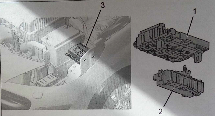
Engine switch box (3) consists of two interconnected modules:
- module 1 contains circuit breakers (2);
- module 2 is equipped with electronic circuitry, fuses and relays (1).
The main functions of the motor switching unit are:
- distribution of power to the nodes located under the engine hood;
- ensuring the joint operation of individual elements in the engine compartment;
- communication with the CAN CAR network;
- receiving signals from sensors located under the engine hood.
Module 1
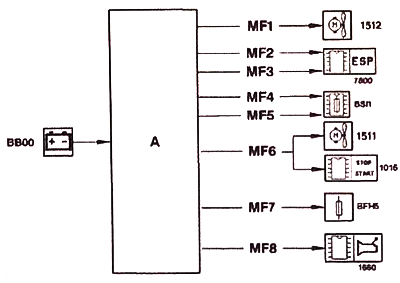
BSM Switching Module 1 Block Diagram
Note. A single arrow in the diagram means the power supply circuit «+BAT».
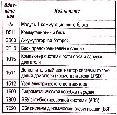
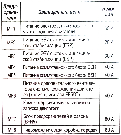
Power fuse circuit
Module 2
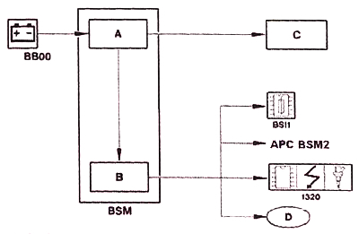
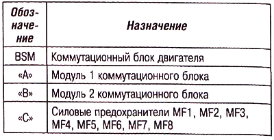
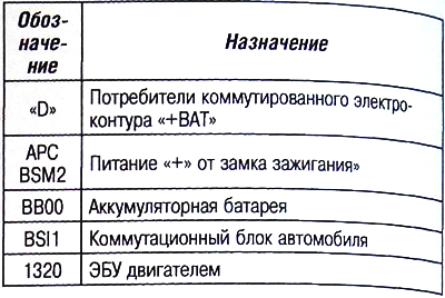
Switching Module Block Diagram 2 BSMs
Operating mode
The electronic unit of the engine management system operates in four modes:
- mode «The system is inactive or in a standby state» - power supply «+ ARS» (engine system interface block) And «+ Change to operating mode» below 5.5 V;
- mode «Power latch» – power supply «+ ARS» And «+ Switching working mode» below 5.5V, the main relay is controlled by the engine computer:
- mode «the system has exited the standby state» - all functions are active. CAN CAR multiplex communication is working;
- Auxiliary mode in case of lack of communication via the CAN CAR multiplex network.
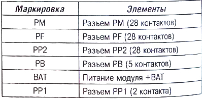
PF connector
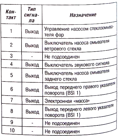
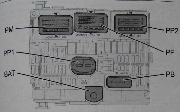
Switching unit module 2
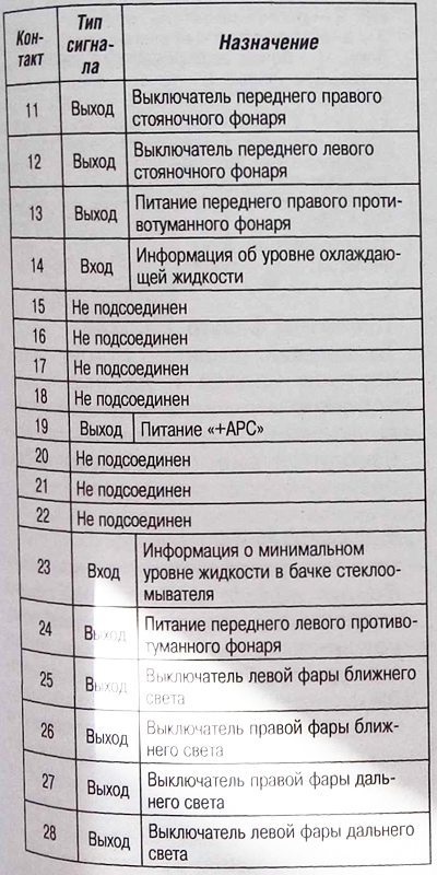
PM connector
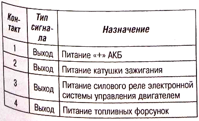
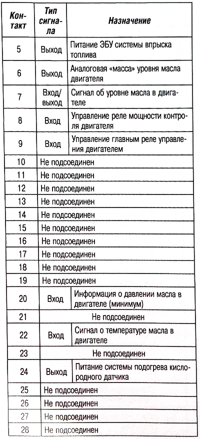
Connector PP1
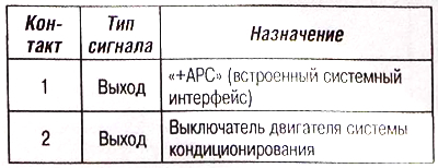
PP2 connector
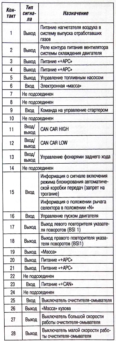
PB connector
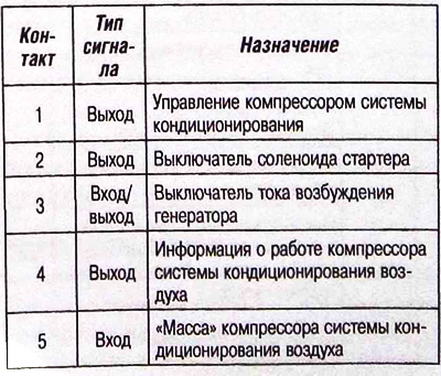
BSI Module 2 Electrical Fuse Marking


