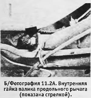
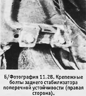
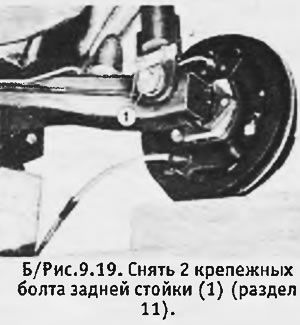
2. Bring the preparation of the machine to the point where the brake pipe, handbrake cable are disconnected (in the cabin). On models with an early brake compensator, unhook the compensator spring from the rear mount. Loosen the nut on the inner end of the trailing arm pin and remove the anti-roll bar mounting bolts (see photo).
 |  |
3. Remove the rear seat and unscrew the 3 nuts with washers securing the cross to the cabin floor. Knock out the studs with a soft-faced hammer in order to move the cross to the bottom. Pull the disconnected handbrake cable through the floor.
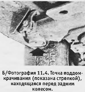
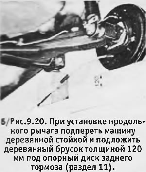
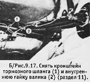
4. Remove the brake hose bracket located near the inner end of the trailing arm and unscrew the inner shaft nut. Remove the rear wheel and support the rear brake platter with a piece of wood 120 mm thick (the machine must rest on a 250 mm high stand installed at the rear jacking point, immediately in front of the rear wheel) (see photo).
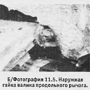
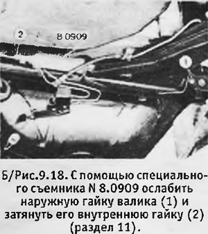
5. If possible, loosen the outer nut of the trailing arm pin with a thin open end wrench (see photo). Install a special puller on the inner end of the roller and tighten the puller nut so that the roller moves inward (towards the center of the car), to remove the outer nut. Remove the outer nut and continue to move the roller with the puller until it comes out (see b/fig. 9.18).
 |  |
6. Bend the petals of the locking plates 2 bolts securing the lower end of the rear rack to the trailing arm. Loosen and remove screws. Remove the trailing arm from the machine.
7. To mount the trailing arm in place, support the machine with a 250 mm wooden stand at the rear jacking point and place the front of the trailing arm between its mountings on the cross. Support the rear brake platter with a piece of wood 120 mm thick.
8. Insert the roller so that it passes through the trailing arm and its fasteners, but its inner end protrudes 42 mm.
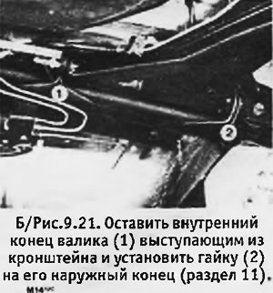
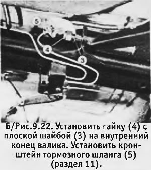
9. Install a new Nylstop nut on the outer end of the roller and a Nylstop nut with a new regular washer on the inner end of the roller. Screw the nuts a few turns without tightening them. Install the brake hose bracket.
 |  |
10. Install 2 bolts with new retaining plates and secure the lower end of the C-pillar to the trailing arm. The bolts do not need to be tightened yet.
11. If required, raise the rear of the machine, insert 3 cross studs into the holes in the floor and install 3 new Nylstop nuts with new plain washers onto the studs. Tighten the nuts to the correct torque.
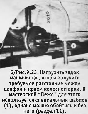
12. Load the rear of the machine so that the distance between the center of the trunnion on the trailing arm and the edge of the wheel arch is approximately 305-315 mm.
13. Hit the end of the roller with a soft-faced hammer to free it, and tighten the outer roller nut to the correct torque, then loosen it 1/4 turn.
14. Screw in the inner nut until it reaches the surface of the bracket and then tighten it to the correct torque.
15. Tighten the 2 bolts of the lower mounting of the rear rack to the desired moment and lock them, bent the petals of the locking plates.
16. Install the brake hose, replacing its clamp with a new one.
17. Install the rear anti-roll bar mounting bolts with new lock washers and tighten the bolts to the correct torque.
18. Unload the rear of the machine and raise it to install the rear wheel. Tighten the wheel nuts to the correct torque.
19. Install the hand brake cable and perform the remaining operations in the reverse order of preparation for removing the lever. Adjust handbrake (see chapter 8), bleed the brake system and adjust the brake compensator (on models with an early type compensator).
