Block and cylinders
1. Inspect the casting of the cylinder block for defects and cracks.
2. Remove 2 plugs if necessary (at the rear of the block and in the flange below the oil filter) and clean the oil line. When finished, install and re-tighten the plugs. To clean the water channels, you can remove the inspection plate at the rear of the unit.
3. Inspect the block plugs for signs of leakage and replace them if necessary. To remove the old plug, drill a small hole in it and drive a self-tapping screw into it, and then, grabbing it, pull out the plug. Alternatively, you can drive a chisel into the plug and pull it out using the chisel as a lever. Clean the plug seat, apply some sealant to it, and hammer the new plug into place using the flat side of the hammer head. Place the plug in place by hitting it in the center with a round-faced hammer.
4. If you suspect that there are cracks in the block, you should have it checked by a specialist.
5. The protrusion in their upper part indicates the wear of the cylinders. An internal micrometer is needed to accurately measure the cylinder diameter, but cylinder wear can be judged using feeler gauges. Insert feeler gauge between piston (without piston rings) and the cylinder wall and compare the clearance between them 8 on the bottom of the cylinder not subject to wear and immediately below the lip. The manufacturer does not set the maximum allowable wear of the cylinder, however, if its ovality or taper is more than 0.1 mm, the cylinder needs to be bored. Also pay attention to scratches and scuffs.
6. When boring cylinders, the workshop usually selects oversized pistons and piston rings on its own.
7. If the cylinders are not worn out enough to need reboring, special oil scraper rings must be installed on the pistons.
Crankshaft and bearings
8. Inspect the crankshaft for damage and excessive wear.
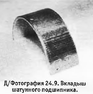
9. Inspect the bearing shells for wear and scratches on the running surfaces. Unless the bearings are practically new, they should be replaced regardless of their condition (see photo).
10. Inspect the crankshaft journals for wear and other defects. The presence of defects may require regrinding of the necks. Using a micrometer, measure the diameter of the necks in several places in order to check for ovality and taper. The manufacturer does not give any maximum allowable values, but usually a taper or ovality of 0.025 mm is considered the maximum allowable.
11. Keep in mind that the crankshaft may have been reground before and that the manufacturer only gives one regrind limit.
12. Main and connecting rod bearing clearances can be worn out with Plastigage thread. Wipe the journal and bearing shells clean and lay the thread across the journal. Install and secure the bearing race, then remove it again and compare the width of the discrepancies with a special scale, which immediately indicates the corresponding operating clearances. The manufacturer does not specify the working clearances, but they must be in the range of 0.025-0.050 mm.
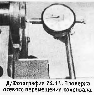
13. Check the axial movement of the crankshaft by inserting a feeler gauge between the bearing thrust washer N 2 and the crankshaft web. If the limit is exceeded, the thrust washers must be replaced. For axial movement of the crankshaft, you can also use a dial gauge.
Pistons, piston rings and connecting rods
14. Piston rings can be removed from the pistons using thin metal strips. Carefully spread the upper ring so that the feeler gauges can be inserted under it and then removed together with the feeler gauges through the piston crown (see photo). Be careful not to scratch the piston with the ends of the ring.
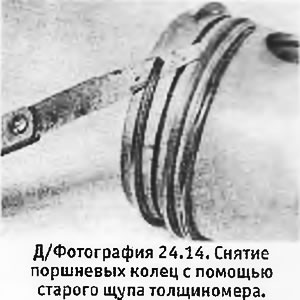
15. Remove the second and third rings in the same way so that the rings do not fall into empty grooves. Please note that the third ring includes an expander that is easier to remove through the piston crown. If you are not going to change the rings, you should put them next to the pistons from which they were removed.
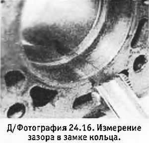
16. Installing the rings one at a time into their cylinders. The clearance must be checked with the ring in any position of the cylinder, or at its very bottom (where cylinder wear is minimal) using a thickness gauge (see photo).
17. If you are going to replace the rings, you should clean the cylinder walls from varnish-like plaque (see section 16).
18. Inspect pistons for damage (especially for burns in the bottom area and scuffs and scratches on the skirt or between the grooves for the rings). 06t, shrunken areas on the sides of the pistons indicate gas breakthrough.
19. If the preliminary inspection showed that the pistons are in order, clean the grooves for the rings with a piece of the old piston ring. Be careful not to expand the grooves and cut yourself.
20. Spin each ring in its groove to see if it's sticking. Excessive ring clearance in the groove, not due to ring wear, can only be caused by wear on the piston itself, and unless the pistons are reground to fit special piston rings, they will have to be replaced.
21. When replacing pistons without reboring the cylinders, check that the new pistons are correctly sized. The piston size class is indicated by either a label "A1". or the complete absence of a mark in the middle part of the piston bottom. A similar marking should be on the corner of the cylinder block (from the timing belt side). The weight class of the piston is stamped on its bottom and must be the same for all pistons in the engine.
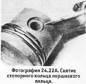
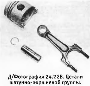
29. In order to disconnect the piston from the connecting rod, remove the circlips and pull out the piston pin (see pictures). In order to remove the finger, it is enough to press on it with your hand. Mark the piston and connecting rod so as not to confuse them during assembly.
 |  |
22. If there is excessive play in the piston pin bushing, both the pin and the bushing must be replaced. The replacement of the sleeve must be carried out by a specialist, because. it requires a press, and in addition, the new sleeve must be correctly expanded in place.
23. New pistons are supplied with piston pins and circlips. Connecting rods usually do not need to be replaced, unless the engine has previously jammed.
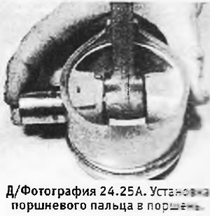
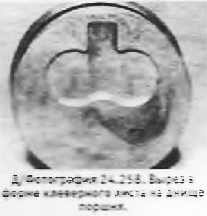
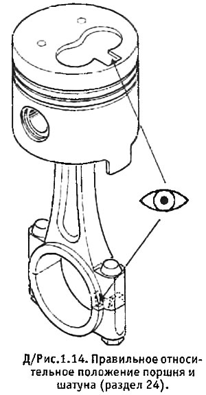
24. Reconnect the pistons to the connecting rods and check that the pistons are correctly installed (The cloverleaf cutout on the piston crown must be on the same side as the cutout on the connecting rod). Before installing the piston pins, they must be lubricated with oil (see pictures). When properly assembled, the piston should turn freely on the connecting rod.
 |  |
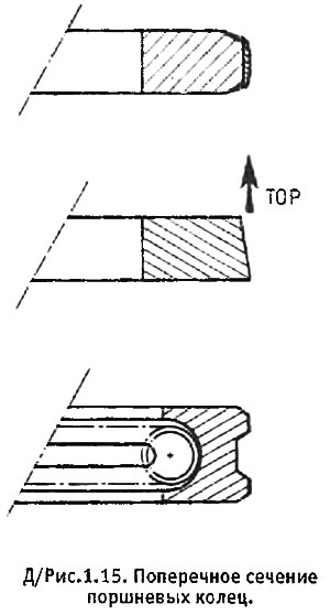
25. Install the piston rings using the same method as when removing them. The bottom ring is installed first. At the oil scraper ring, an expander is first installed, and then the ring itself, the lock of which must be displaced at an angle of 180°with respect to the expander lock. The locks of the two upper rings must be displaced by 120°in opposite directions from the lock of the oil scraper ring. Check that ring no. 2 is facing up (see d/fig. 1.15).
 |  |
Oil pump
26. See section 14.
Timing belt and sprockets
27. See section 4. Sprockets should be inspected for wear or damage.
Camshaft
28. See section 7.
Cylinder head
29. See section 10.
Flywheel
30. Inspect the surface of the flywheel that is in contact with the clutch for abrasion and cracks. Minor striations or scratches are normal. Surface cracks and deeper grooves can sometimes be removed by resurfacing, provided that the flywheel thickness does not decrease below an acceptable value. If this is not possible, the flywheel should be replaced.
31. Inspect the starter ring gear for damage and chipped teeth. If necessary, the crown can be replaced separately from the flywheel. Drill a full-thick hole in the crown and then split it with a chisel and remove. The new crown must be heated, quickly installed on the flywheel, hammered into place and left to cool naturally. The temperature to which the crown is heated is of critical importance: at too low a temperature, the crown may not fit into place or get stuck halfway; at too high, the hardening of the crown may be lost, which will lead to its rapid wear. The heating temperature is usually indicated in the instructions that come with the new crown, but we still recommend entrusting this work to a specialist.
Other
32. The manufacturer recommends that only the flywheel bolts be replaced when overhauling the engine, but we recommend replacing the cylinder head bolts as well, especially if they have been tightened more than once.
Oil Cooler Mount - All Models
33. Since the end of 1990, improvements have been made to the oil cooler mount so that it stays in place when the oil filter is removed. The cylinder block has a locking lug that fits into the plug on the oil cooler.
34. In the case of early models that do not have a special locking lug, it is possible to purchase a locking bracket that is bolted to the cylinder block and effectively prevents the oil cooler from rotating.
35. Before removing the oil cooler, you must first remove the oil filter.
36. Remove the filler plug of the cooling system (with a cold engine). Disconnect the coolant hoses from the filter (be prepared to spill fluid and plug hoses immediately to avoid further fluid loss).
37. Remove the oil filter mounting stud and remove the oil cooler from the engine.
38. Installing the oil cooler is done in reverse order. Pay attention to the following points:
- A. When installing the oil cooler, make sure that its plug fits into the protrusion on the cylinder block (or, depending on the design, under a special bracket on the side of the cylinder block).
- b. Before installing the oil filter mounting stud, thoroughly clean its threads and coat with a suitable threadlocker.
- V. Tighten the mounting stud to the correct torque (see specs).
