2. If you still decide to disassemble the carburetor, remember that it requires the most careful handling. Be careful not to confuse the jets and in no case clean them with wire so as not to knock down the calibration.
3. Before disassembling the carburetor or any part of it, the carburetor must be thoroughly cleaned from the outside. Remember the position of individual parts so that you can later install them exactly in place. It is best to mark the parts or lay them out in the order they were removed.
4. Find on B / fig. 3.4, 3.5, 3.10 and 3.11 the desired carburetor. Remove the top cover of the carburetor by unscrewing the 6 fixing screws. Pull out the float shaft and remove it. Unscrew the needle valve from the cover. Unscrew the fuel inlet fitting and remove the strainer. Inspect the filter for contamination.
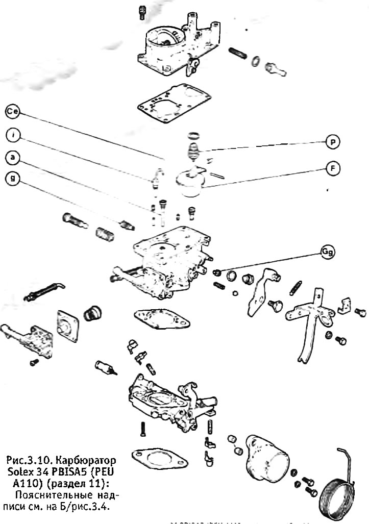
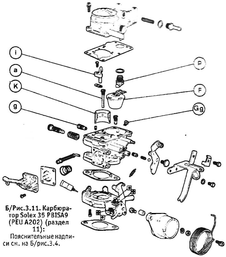
5. Remove the thrust of the drive mechanism of the accelerator pump, gradually unscrew the 4 fixing screws, making sure that the pump cover is not warped under the pressure of the spring standing under the diaphragm and remove the cover. Inspect the diaphragm for cracks and damage.
6. Remove the accelerator pump inlet valve cover located at the bottom of the float chamber, being careful not to drop the ball valve. Inspect the filter for contamination.
7. Unscrew and remove the jets, inspecting them for clogging.
8. Adjustment screws usually do not need to be touched, but if you do, you should calculate how many turns each screw will have to turn to remove it, so that when assembling, set the screw to approximately its original position.
9. Do not touch the air and throttle valves or their shafts. Damper actuators are external and generally do not require attention (unless they are very worn out). If the throttle pins are worn in the part that is in the body of the carburetor, it may be necessary to replace the carburetor assembly. This type of wear is indicative of general carburetor wear that cannot be repaired. Air leaks around worn throttle shafts make it difficult to adjust the carburetor, which will inevitably lead to poor engine performance.
10. Chambers, channels and jet seats can be cleaned with a brush dipped in clean gasoline and then dried with compressed air. In the absence of a source of compressed air, they should be allowed to dry naturally (do not use rags). Rinse the jets in clean gasoline and blow them out with compressed air.
11. The carburetor is assembled in the reverse order. Install new washers, gaskets and seals whenever possible. Check and adjust the top position of the float (see section 8) and adjust the stroke of the accelerator pump (see section 9). Upon completion, check and, if necessary, adjust the position of the accelerator pump sprayer (see section 9). After installing the carburetor in place, check and adjust the idle speed (see section 7).
Solex 32-35 TACIC carburetor - disassembly and assembly
1. See above for general instructions for disassembling the carburetor. The carburetor device is shown in B/fig. 12.22.
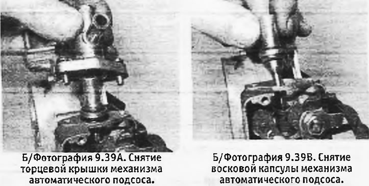
2. Do not disassemble the auto-choke mechanism more than necessary. The wax capsule can be replaced after removing the end cap and gasket. When assembling, the gasket must be replaced with a new one (see pictures).
3. Before assembling the carburetor, check and, if necessary, adjust the upper position of the float. Replace all gaskets with new ones and install a new O-ring on the adapter system.
4. Before installing the carburetor, check the normal position of the throttle valves at idle. This will require precision measuring instruments and therefore it is better to entrust this operation to a specialist.
Solex Z type carburetor - disassembly and assembly.
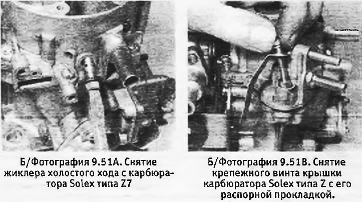
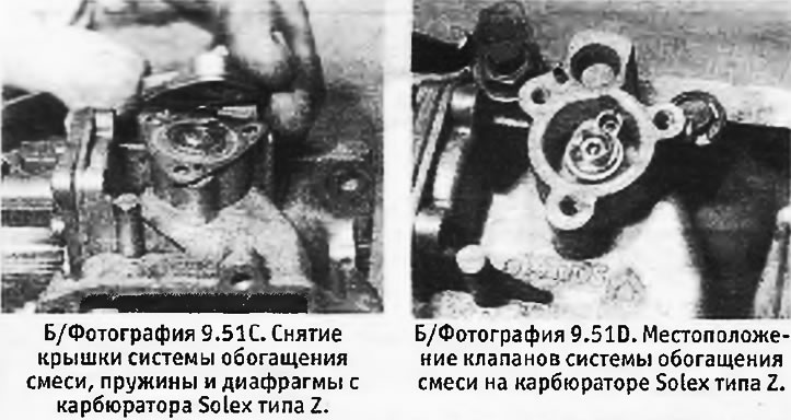
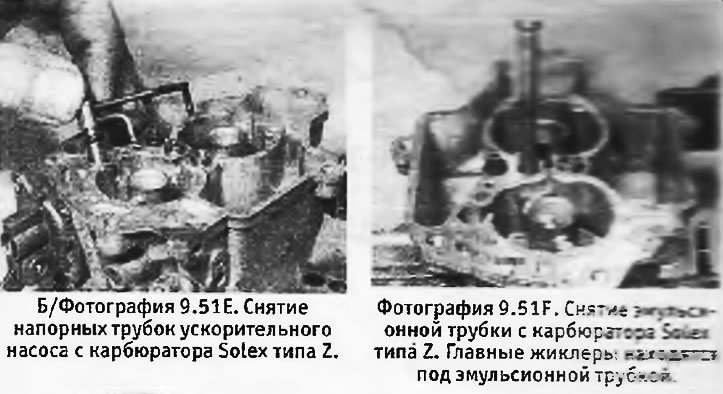
5. Refer to the 32-35 TACIC Carburetor Disassembly and Assembly procedure. The carburetor device is shown in the attached photographs.
