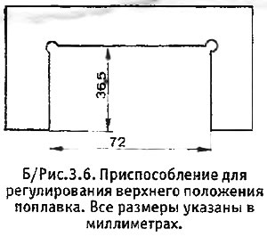
2. Focusing on B / fig. 3.6, make a fixture according to the dimensions indicated in the figure, using tin or plastic. The material is not so important - dimensions are critical, so you need to be especially careful here.

3. The top position of the float should be checked before assembling the carburetor after routine maintenance or when the fuel level in the float chamber is in doubt. Carburetor flooding is almost always caused by a clogged needle valve or a leaky float, although in some cases it may be due to improper float up adjustment.
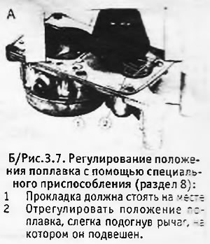
4. Turn the upper half of the carburetor over, check that the gasket is in place and attach the tool to the surface of the upper half of the carburetor that turned out to be at the top. With the needle valve closed, the float should just touch the fixture (see b/fig. 3.7).

5. If necessary, adjust the position of the float by slightly bending the lever on which it is suspended. This should be done carefully, constantly checking the position of the float with a tool.
Float Top Adjustment - Solex Carburettors on Latest Models
1. In the case of the latest models, the lever on which the float is suspended may be plastic. In this case, it cannot be bent. The top position of the float is adjusted by changing the number of washers under the needle valve.
2. In the case of a 32-35 TACIC carburetor, at the top float adjuster (see b/fig. 3.6) the distance between the supports is 80 mm, and the cutout depth is 41 mm. In the case of a Z-type carburetor, these dimensions are 70 mm and 33.5 mm, respectively.
Float Top Adjustment - Weber Carburettors
34 IBP and 32/34 DRTC4 100
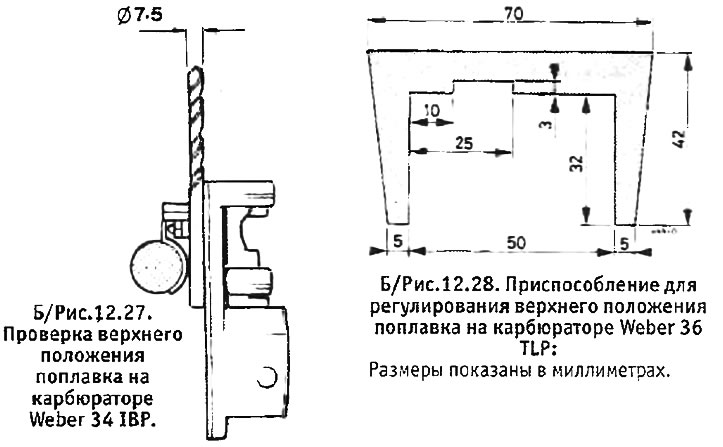
3. To check the top position of the float, remove the cover of the float chamber and set it vertically so that the float hangs down. With the gasket in place and the float lever resting on the ball of the needle valve, the 7.5 + 0.5 mm drill should just pass between the float and the gasket. (Do not measure this gap where the float seam passes). To adjust the position of the float, carefully bend the lever on which it is suspended.
36 TLP
4. Make a device for checking the upper position of the float (see 6/fig. 12.28).

5. Remove the float chamber cover. Check that the gasket is in good condition and securely held in place.
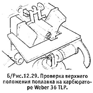
6. Install the cover vertically so that the float hangs down. Bring a homemade device to the lid, as shown in B / fig. 12.29. The float should just touch the fixture. If necessary, adjust the position of the float by slightly bending the adjusting tongue and connecting rods.

7. Replace the float chamber cover.
