137. Apply sealant to the contact surface and install the differential box with bearing rings (see photo).
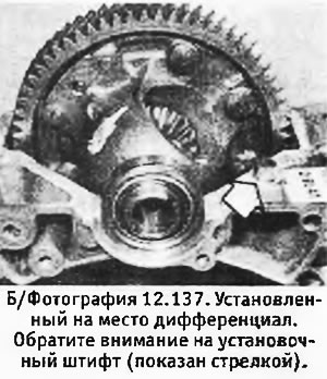
138. Install the half final drive housing and extension and at this stage tighten their fixing screws by hand.
139. Install a new oil seal, lubricating its sponges well, on that surface of the final drive housing, which is more distant from the extension.
Early models (with shim for adjusting bearing preload)
140. Remove the extension, install a 2.2 mm shim on the outer race of the bearing and reinstall the extension (without its o-ring). While tightening the extension mounting bolts, turn the driven gear until resistance is just felt. This operation will seat the bearings.
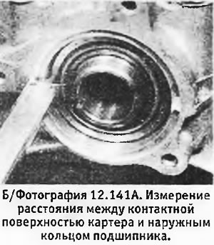
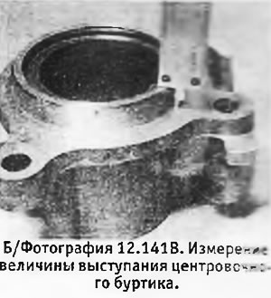
141. Remove the extension and shim and use an accurate depth gauge to measure the distance from the contact surface of the final drive housing to the bearing outer race (distance "A"). Similarly, measure the protrusion of the centering shoulder on the extension above the contact surface of the extension (distance "IN").
 |  |
142. The thickness of the shim is determined by the formula:
S = (A - B) + 0.10 mm
An additional 0.10 mm determines the bearing preload. Adjusting shims are available in thicknesses of 1.1-2.2 mm with OD mm increments.
143. Tighten the final drive housing mounting bolts to the correct torque.
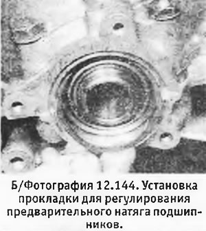
144. Install an adjusting shim of the desired thickness, the speedometer drive gear and an extension with a new sealing ring. Tighten the fixing bolts to the correct torque (see photo). Check that the driven gear can rotate freely.
Latest Models (without shim for adjusting bearing preload)
145. Models that do not require a shim to adjust the bearing preload can be identified by the length of the shoulder on the extension (see B/fig.12.66). If this shoulder is 10 mm long, no spacer is needed. With a length of 8.65 mm, a shim is required to adjust the bearing preload.
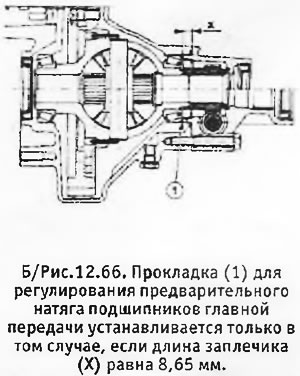
146. Install the speedometer drive gear (if filmed). Install the extension with a new O-ring. Gradually tighten the extension bolts while rotating the pinion gear to seat the bearings.
147. Tighten the bolts of the final drive housing and extension to the desired torque.
All models
148. Install and secure the speedometer toothed roller with its adapter. Install a new oil seal in the extension, lubricating its sponges well. Install a new gear shift shaft seal into the main crankcase.
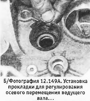
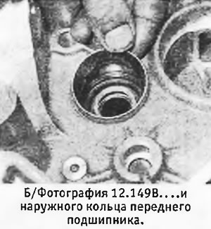
149. Working from the clutch housing side, install the release bearing guide tube (without pipe flange gasket). Tighten the tube by hand, turn the crankcase over and install the shim to regulate the axial movement (any available thickness) and the outer ring of the bearing of the drive shaft (see pictures).
 |  |
150. Install the shift shaft spring bracket and tighten its mounting bolts to the desired torque.
151. Install 2 dowel pins on the contact surface of the main crankcase (if filmed).
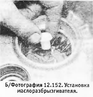
152. Install and tighten the breather (where applicable). Install oil sprinkler (see photo).
153. Install the reverse gear lock spring and plunger. Press the plunger and install the reverse fork with its stem. Tighten the stem retaining nut to the correct torque.
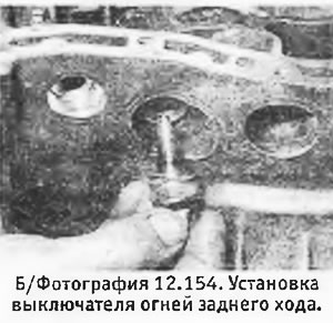
154. Install the reverse light switch with a new copper washer and tighten it to the desired torque (see photo).
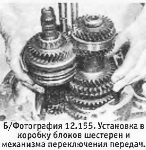
155. Assemble gear blocks with forks and gear shift rods and install the assembled unit in the gearbox housing (see photo).
156. Install the reverse gear axle with the gear so that the chamfer on the gear looks at the rear end of the gearbox. Check the correct position of the pin on the axle.
157. Install a magnet to collect metal dust.
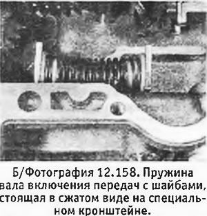
158. Insert a spring with washers into the bracket (see photo).
159. Insert the gear shift shaft into the crankcase by passing it through a compressed spring with washers inside the crankcase. Insert the shaft into the switch pin and locking bracket. We recommend keeping the pin with the bracket on a short bar (with a maximum diameter of 14 mm), which can be pulled out as the shaft is inserted (see photo).
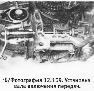
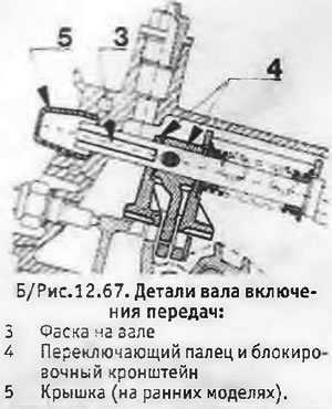
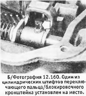
160. Check that the chamfer on the shaft and the roll pin hole are in the correct position (see B/fig.12.67). Secure switch pin and locking bracket to the shaft with 2 new roll pins. The slots on the pins must be 180°apart from each other and parallel to the longitudinal axis of the shaft (see photo).
 |  |
161. On the latest models, install a washer and a retaining ring on the end of the shaft from the side of the cover.
162. On all models, install the gear shift shaft cover (if decreased).
163. Install a new o-ring, washer and new circlip on the lever end of the shaft.
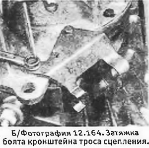
164. Apply sealant to the mating surfaces of the main case/end cap. Install the end cap, making sure the input and output shafts and stems fit through their holes. Install the 13 mounting bolts and gradually tighten them to the correct torque. Don't forget to install the clutch cable bracket (see photo).
165. Install the reverse idle gear axle bolt with a new washer. Tighten the bolt to the correct torque.
166. Install drain plug (traffic jams) with new washer (washers) and tighten it (their) until the right moment.
167. Install the lock plate of the gear selection rod and secure it with a bolt and washer, tightening the bolt to the desired torque.
168. Install the output shaft bearing circlip, making sure it fits correctly in its groove.
169. Install the output shaft rear bearing retaining bolts with washers. Tighten the bolts to the correct torque.
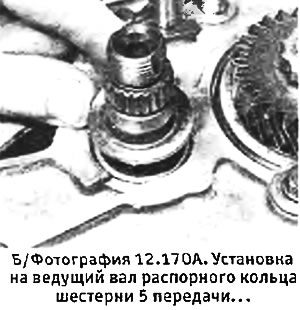
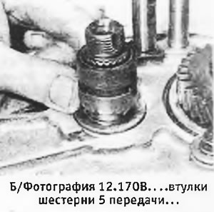
170. Install a spacer ring on the drive shaft (shoulder towards the bearing), the 5th gear bushing and the 5th gear itself. Install the 5th gear synchro clutch and hub. The plug does not need to be installed yet (see pictures).
 |  |
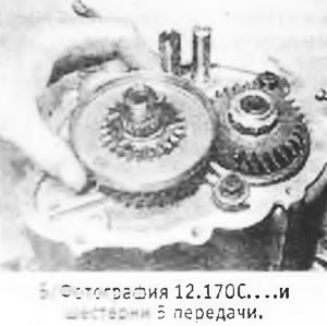
171. Lock the gear blocks by engaging 5th gear using the synchronizer clutch and any other gear using the gear shift shaft. Install the output shaft nut and tighten it to the correct torque, and then lock it by driving its collar into the groove.
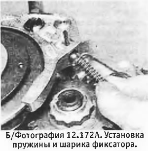
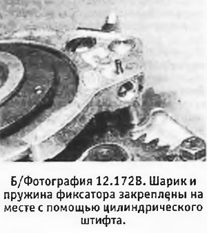
172. Remove the clutch and hub of the 5th gear synchronizer, and then reinstall them, but with a fork. If you have not replaced parts, you should make sure that the marks made during disassembly are aligned. In the process of lowering the fork into place, insert the retainer ball into the hole intended for it. Alternatively, you can pull out the roll pin and insert the detent ball and spring from the other end (see pictures).
 |  |
173. Re-engage the 2 gears and then install the drive shaft nut. Tighten the nut to the correct torque and lock it by driving its collar into the groove.
174. Fix the 5th gear fork on its stem with a new cylindrical pin.
175. Cover the contact surfaces with sealant and install the rear cover. Coat the threads of its bolts with thread locking compound and tighten the bolts to the correct torque.
176. Rotate the clutch housing and remove the release bearing guide tube. If you are going to replace the clutch release lever ball joint, it should be done now. Apply a thread locking compound to the hinge splines and hammer it into place.
177. Install the release bearing guide tube with a washer that regulates axial movement (thickness 2.4mm), and without padding. Insert the fixing bolts and gradually tighten them while rotating the drive shaft. Stop tightening the bolts when resistance is just beginning to be felt during the rotation of the shaft (those. when the bearings are properly seated).
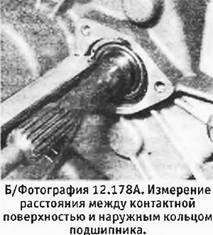
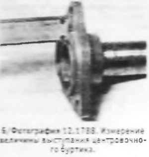
178. Remove the guide tube with the adjusting washer. Using an accurate depth gauge, measure the distance from the outer race of the bearing to the contact surface of the crankcase (distance "WITH"). Similarly, measure the protrusion of the centering shoulder on the flange of the guide tube above the contact surface (distance "D").
 |  |
179. Necessary thickness "T" shim is determined by the formula:
T = (C -D) + 0.03 mm
An additional 0.03 mm ensures correct axial movement and gives a tolerance for the thickness of the gasket to be installed. Adjusting washers are available in thicknesses of 0.7-32.4 mm in increments of 0.1 mm.
180. Install a new oil seal on the guide tube, lubricating its lips well.
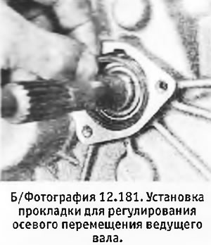
181. Install the washer to regulate the axial movement (desired thickness), new gasket and guide tube. Fasten the tube with bolts and tighten them to the desired torque (see photo).
182. Install the clutch release fork and release bearing.
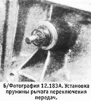
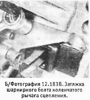
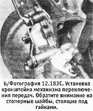
183. If not already done, install the shift levers, making sure they are in the correct position (see b/fig. 12.51). Install crank clutch (if filmed) and gearshift bracket (see pictures).
 |  |
184. The assembly of the gearbox is completed. Oil is poured into the box only after the installation of the drive shafts.
