Attention! Remove and install the instrument panel with care. When removing, make sure that all electrical connectors are completely disconnected. When reinstalling, make sure the wiring harnesses are properly routed and secured.
To remove the instrument panel:
- cover the front seats;
- turn off the ignition and disconnect the wire «masses» from the storage battery;
- move the front seats all the way back;
- set the wheels to drive straight ahead and lock the steering lock;
- remove the lower part of the central panel and the ashtray body;
- remove the center console;
- remove the upper part of the center console and the central ventilation grille;
- remove the temperature sensor in the car;
- remove the instrument cluster;
- remove the multifunction display;
- remove the upholstery panels of the front pillars;
- in the depth of the socket of the multifunctional display, unscrew the fixing bolt in the upper part of the air conditioner;
- remove the brightness sensor from the instrument panel;
- using a plastic spatula, remove the side ventilation grilles;
- remove the cover of the electrical fuse box and trim panel 2 under the steering column, releasing them from the latches and pulling down;
- remove the airbag from the driver's side;
- disconnect the electrical connector at the bottom under the steering wheel;
- loosen the steering wheel bolt a few turns;
- move the steering wheel from the slots, if necessary, hitting with your hands from the back side along its perimeter;
- turn out a bolt of fastening of a steering wheel;
- with chalk, marker or paint, apply alignment marks A on the steering wheel and the end of the steering shaft. Tags are necessary to reinstall the steering wheel in its original position;
- disconnect from a steering wheel electric sockets;
- remove the steering wheel, having previously passed the electrical connectors one by one through the cutouts in the steering wheel;
- unscrew the screws securing the casings of the steering column, located under the lower casing;
- remove the lower casing of the steering column;
- release the upper casing of the steering column from the latches and remove it;
- remove the steering column switch block COM 2000;
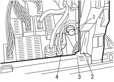
Pic. 10.62. Fastening of the intelligent switching unit: 1 - latch; 2, 4 - connectors; 3 - fastening brackets
- on each side of the smart junction box, release the latches 1 (pic. 10.62), turning them a quarter of a turn, remove the lower brackets 3 of the fasteners and tilt the unit away from the instrument panel;
- release the electrical connector 2 of the intelligent switching unit from the latches and disconnect it;
- unplug the black 6-pin electrical connector to the right of the smart junction box;
- release and disconnect the green 2-pin electrical connector;
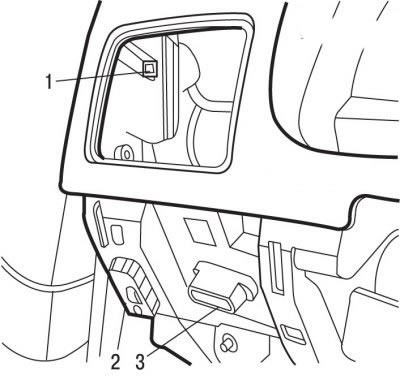
Pic. 10.63. Connector Location: 1 - upper latch of the side covers for fastening the instrument panel; 2 - headlight corrector connector; 3 - diagnostic electrical connector
- disconnect the diagnostic electrical connector 3 (pic. 10.63);
- disconnect an electric socket 2 of the corrector of light of headlights;
- sticking your hand through the holes of the side ventilation grilles, move the upper latch 1 of the side covers for attaching the instrument panel;
- remove the side covers of the instrument panel mounting;
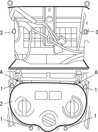
Pic. 10.64. Air conditioning mount: 1 - screws; 2 - control panel for the air conditioning system; 3 - bolts for fastening the cross member of the panel; 4 - clamps
- remove four screws 1 (pic. 10.64) fixing the control panel of the air conditioning system;
- release from the clamps at points A (see fig. 10.64) air conditioning control panel;
- turn out two bolts 3 fastenings of a crosspiece of the panel of management of an air conditioning system;
- move away from the control panel of the air conditioning system the wiring harness going to the instrument panel;
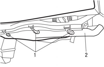
Pic. 10.65. Location of latches (1) fastening trim elements (2) under the dashboard
- release clips 1 and remove trim elements 2 (pic. 10.65) under the instrument panel;
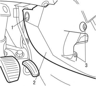
Pic. 10.66. Center console mount: 1 - latch; 2 - side wall of the center console; 3 - bolt
- remove bolts 3 (pic. 10.66), release the clips 1 and remove the side walls 2 of the center console;
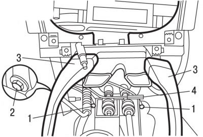
Pic. 10.67. Location of console elements: 1 - bolts of connection with «weight»; 2 - bottom mounting of the amplifier on the tunnel; 3 - air supply pipes; 4 - electrical connector
- disconnect and remove pipes 3 (pic. 10.67) air supply;
- turn out two bolts 1 of connection with «weight», located to the right and left of the shift cables;
- disconnect the black 1-pin electrical connector 4;
- unscrew the bolt 2 of the lower mounting of the amplifier on the tunnel;
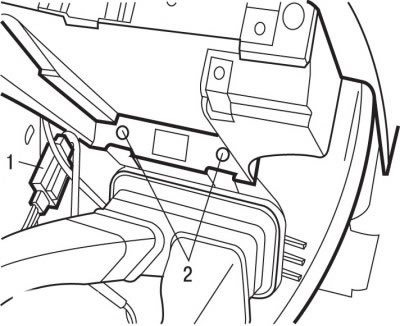
Pic. 10.68. Bolt location (2) instrument panel lower mounting and electrical connector (1)
- remove two screws 2 (pic. 10.68) lower mounting of the instrument panel;
- release from the latches and disconnect the black electrical connector 1 on the extension;
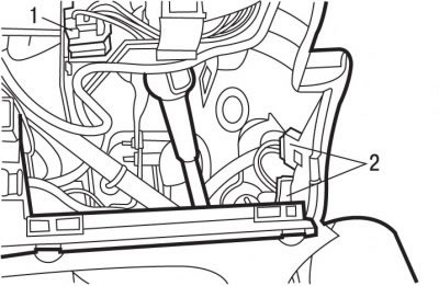
Pic. 10.69. Location of electrical connectors (1 and 2)
- release from clamps and disconnect electrical connectors 2 (pic. 10.69);
- unscrew the four bolts securing the steering column to the cross member on the instrument panel;
- release from the latch and disconnect the electrical connector 1 green, fixed on the cross member of the steering column;
- unscrew the bolt of the instrument panel cross member, located in the depth of the instrument panel socket;
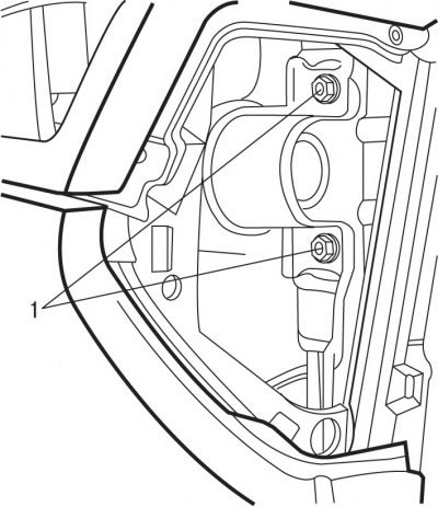
Pic. 10.70. Bolt location (1) fastening the cross member of the instrument panel to the body
- unscrew the two side bolts 1 (pic. 10.70) fastening the cross member of the instrument panel to the body;
- two people are needed to remove the instrument panel from the guide pins;
- raise the instrument panel, while making sure not to pull the wiring harnesses;
- remove the instrument panel through the driver's door.
To install the instrument panel:
- check the correctness of the wiring harnesses and the location of the electrical connectors;
- Installation is carried out in the reverse order of removal, taking into account the following:
- tighten bolts 1 (pic. 10.70) fastening the cross member of the instrument panel to the body with a torque of 10 Nm;
- tighten the bolts securing the steering column to the instrument panel crossmember to 22 Nm;
- screw in the instrument panel cross member mounting bolt located deep in the instrument panel socket and tighten it to 24 Nm;
- screw in bolt 2 (see fig. 10.68) the lower fastening of the amplifier on the tunnel and tighten it with a torque of 24 Nm;
- screw in the steering wheel mounting bolt and tighten it to 33 Nm.
