- press the brake pedal several times with the engine off to create the same pressure in the cavities of the vacuum booster, close to atmospheric;
- by the force applied to the pedal, determine if there is any jamming of the valve body;
- stop the brake pedal in the middle of its travel and start the engine. With a working vacuum booster, the brake pedal should go forward after starting the engine;
- if the pedal does not go forward, check the fastening of the hose tip, the condition of the fastening of the tip flange in the amplifier, the condition of the hose and fitting;
- on vehicles with diesel engines, also check that the vacuum pump is working properly.
Attention! When installing, it is necessary to install new sealing rings on the vacuum brake booster and brake master cylinder and axle 2 (see fig. 8.5). Check whether the push rod of the brake booster returns freely, the stroke of which is (19,85±1,3) mm (this dimension is determined between the pressure plane of the main brake cylinder and the push rod head).
To remove the vacuum brake booster:
- remove the decorative battery cover;
- remove the mudguard of the left front wheel arch;

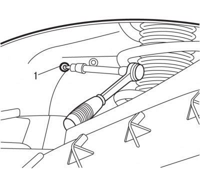
Pic. 5.20. Removing a bolt (1) battery support mountings
- from under the arch of the left front wheel, unscrew the bolt 1 (see fig. 5.20) fastening of a support of the accumulator battery;
- remove the battery;
- remove the battery support;
- remove the master brake cylinder;
- release from the clamps and take aside the harnesses of electrical wires;

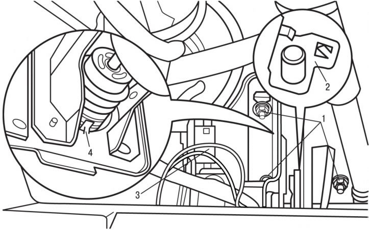
Pic. 8.5. Mounting elements of the pedal assembly bracket: 1 - nuts, 20 Nm; 2 - axis; 3 - pedal assembly bracket; 4 - clamp
- remove axle 2 (pic. 8.5);
- turn out four nuts 1 fastenings of an arm of a pedal knot 3;
- release clamps 4 and remove the pedal assembly;

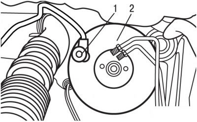
Pic. 8.6. Vacuum hose connection (1) to vacuum brake booster (2)
- Disconnect the vacuum hose 1 from the vacuum brake booster 2 (pic. 8.6);
- Remove the vacuum brake booster.
To install the vacuum brake booster:
- install new sealing rings on the vacuum brake booster and the main brake cylinder;
- lubricate axle 2 (see fig. 8.5).
Further installation is carried out in the reverse order of removal, taking into account the following:
- install the master brake cylinder;
- remove air from the brake system and hydraulic clutch drive;
- tighten the nuts of the pedal assembly bracket to 20 Nm.
