- turn off the ignition and disconnect the wire «masses» from the storage battery;

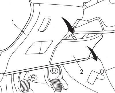
Pic. 9.5. Fuse box location: 1 - cover; 2 - finishing panel
- remove cover 1 (see fig. 9.5) fuse box and trim panel 2 under the steering column, releasing them from the latches and pulling down;
- remove the lower casing of the steering column;
- lift the upper casing of the steering column;

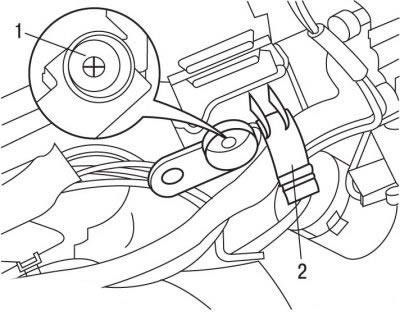
Pic. 9.28. Bolt location (1) and staples (2) ignition lock mounting
- slide the ignition switch off the mounting bracket 2 (pic. 9.28);
- make a mark in the center of the bolt head 1 using a center punch;
- drill a bolt with a drill with a diameter of 3 mm, to a depth of 7-8 mm and unscrew the bolt with a puller;

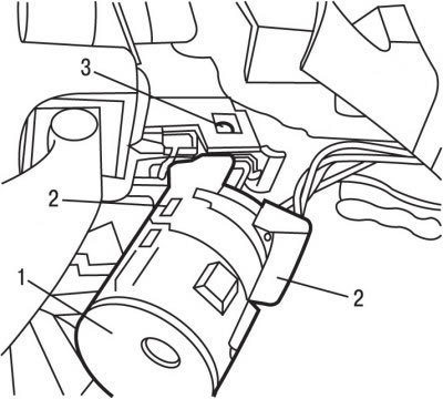
Pic. 9.29. Fastener locations: 1 - immobilizer antenna mount; 1 - clamps; 3 - ignition lock stopper
- lift 2 tabs 2 (pic. 9.29) and remove the immobilizer antenna 1;
- insert the key into the ignition lock and turn it to the first position;
- press the stopper 3 with a blade of a flat screwdriver and remove the ignition lock from the steering column;

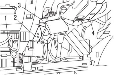
Pic. 9.30. Ignition switch wiring harness location: 1, 3 - electrical connectors; 2, 4 - clamps of the ignition switch wiring harness supports
- release the electrical connector 3 from the clamps (pic. 9.30) ignition lock;
- release from the clamps of the support 2 and 4 of the wiring harness of the ignition switch;
- move aside the ignition switch wiring harness. Cut the retaining straps if necessary;
- disconnect electric sockets 1 and 3;
- Remove the ignition switch along with the wiring harness.
Installation is carried out in the reverse order of removal, taking into account the following:
- connect wire «masses» to the battery;
- check the operation of the ignition switch;
- initiate all electronic systems.
