Attention! Chalk, marker or paint mark the direction of rotation of the toothed belt. If the toothed belt rotates in the opposite direction during installation, this will lead to its destruction.
Removing
Disconnect the wire from the negative battery terminal.
Remove the right front wheel.
Remove the right front wheel arch mudguard.
Remove the accessory drive belt.
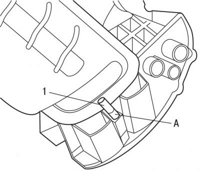
Pic. 4.14. Installing a special tool (1) into the hole in the block (A) crankshaft main covers
Insert special tool 1 (pic. 4.14), fixing the crankshaft from turning into the hole located on block A of the crankshaft main covers.
Remove the accessory drive belt pulley.
Release the wiring harness and move it away from the timing belt cover.
Remove the upper and lower toothed belt covers.
Attention! Pulley track B (see fig. 4.15) should not show signs of damage, and magnetized objects should not be brought close to it. Otherwise, replace the crankshaft pulley.
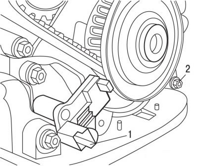
Pic. 4.15. Sensor location (1) engine speed, bolt (2) and magnetic track (IN) on the crankshaft pulley
Remove the engine speed sensor 1 (pic. 4.15).
Turn out a bolt of 2 fastenings of an angular bracket limiting displacement of a toothed belt.
Reinstall the attachment drive pulley bolt.
Remove tool 1 (see fig. 4.14), fixing the crankshaft from turning.
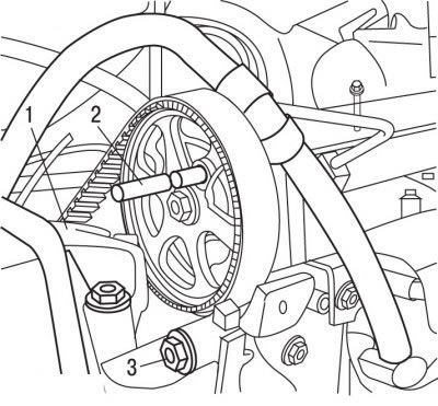
Pic. 4.16. Location right (1) and intermediate (3) engine mounts and special tool (2) locking the camshaft from turning
At the accessory drive pulley bolt, turn the engine crankshaft clockwise so that the holes on the camshaft timing belt pulley and the cylinder head align, and install the special tool 2 (pic. 4.16), fixing the camshaft from turning.
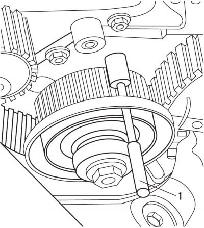
Pic. 4.17. Using a special tool (1) for fixing the crankshaft timing belt pulley
Fix the toothed belt pulley located on the crankshaft by inserting the special tool 1 (pic. 4.17) through the hole in the pulley and oil pump housing.
Place a wooden jack under the engine oil pan and lift the engine to remove the right support.
Remove the right engine support 1 (see fig. 4.16) and intermediate support 3.
Attention! Do not twist or bend the toothed belt. Do not expose the toothed belt to oil, coolant or fuel. If the outer surface of the toothed belt is significantly worn or split, check the condition of the idler and idler roller raceways. If there are any defects on the toothed belt, it must be replaced.
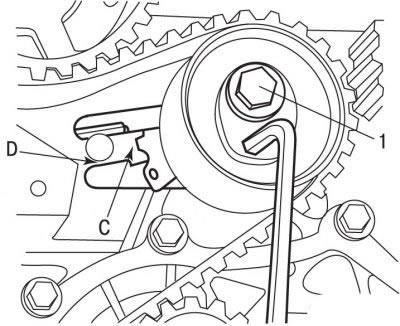
Pic. 4.18. Bolt location (1) tension pulley mounting: C - alignment mark; D - control zone
Loosen bolt 1 (pic. 4.18) fastening the tension roller, holding it from turning with a hex curved wrench. Release the hex key, this will reduce the tension of the toothed belt.
Remove the toothed belt.
Installation
Check that the water pump, idler and idler rollers rotate smoothly and evenly.
Tighten the guide roller mounting bolt to 35 Nm.
Tighten the tension roller mounting bolt to 25 Nm.
Check the tightness of the O-rings at the level of the oil pump and camshaft.
Install while pulling the toothed belt over the pulleys in the following order:
- crankshaft;
- guide roller;
- camshaft;
- high pressure fuel pump;
- water pump;
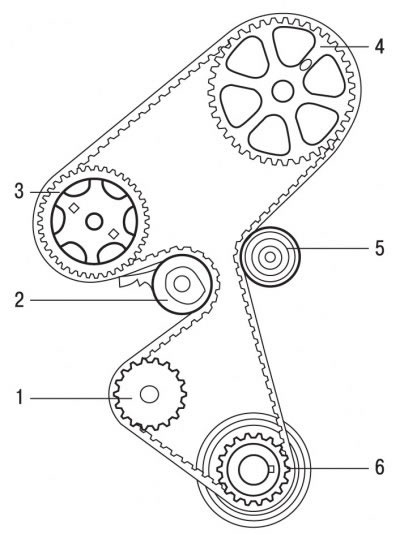
Pic. 4.19. The location of the toothed belt on the pulleys: 1 - water pump; 2 - tension roller of the dynamic tensioner; 3 - high pressure fuel pump; 4 - camshaft pulley; 5 - guide roller; 6 - crankshaft pulley
- tension roller 2 (pic. 4.19).
Install the previously removed belt in accordance with the marked marks.
Reinstall the angle bracket that limits the displacement of the toothed belt and secure with bolt 2 (see fig. 4.15), tightening it with a torque of 5 Nm.
Loosen bolt 1 (see fig. 4.18) fastening the tension roller, holding it from turning with a hex curved wrench.
By turning the tension roller clockwise with a hex wrench, set the mark C (see fig. 4.18) in the middle of the control zone D.
Tighten the tension roller mounting bolt to 25 Nm.
Remove the devices that fix the crankshaft and camshaft from turning.
Rotate the engine crankshaft 10 revolutions.
Install the tools that fix the crankshaft and camshafts from turning.
Make sure the C mark of the dynamic tensioner is in the middle of the control zone. Otherwise, repeat the steps to install the toothed belt.
Remove the devices that fix the crankshaft and camshaft from turning.
Install the speed sensor and secure with a bolt, tightening it with a torque of 5 Nm.
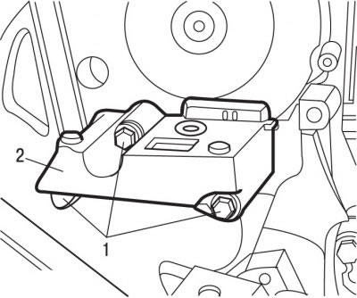
Pic. 4.20. Bolt location (1) engine mount mounts (2)
Install intermediate engine mount 2 (pic. 4.20) and fix it with screws 1.
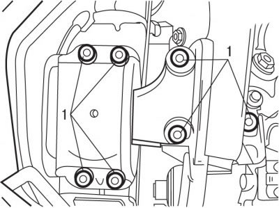
Pic. 4.21. Bolt location (1) right engine mount bracket (2)
Install right engine mount bracket 2 (pic. 4.21) and fix it with screws 1.
Establish the lower casing of a gear belt.
Install a special device that fixes the flywheel from turning.
Loosen the accessory drive belt pulley bolt and then tighten it to 30 Nm and tighten it to an angle (180±5) °.
Remove the special device that fixes the flywheel from turning.
Install the accessory drive belt.
Install the front right mudguard.
Install the front right wheel.
Establish the top casing of a gear belt.
Attach the electrical harness to the top timing belt housing.
Connect the wire to the negative terminal of the battery.
