Recommendations for removing the power unit
Please read this section carefully before starting work.
If the engine is removed for repair, it is necessary to select a place for work, provide space for maintenance and storage of spare parts. Repairs are recommended to be carried out at a workshop or in a garage with a flat, horizontal floor with a clean hard surface.
Clean and wash the engine and engine compartment before removal. To remove, use a lifting device that allows you to safely lift the power package.
If you are removing the power unit for the first time, you must invite an experienced specialist. Some work should be done with an assistant.
All clamps and clamps that are damaged or cut when removing the engine are replaced with new ones when assembling the engine.
Depending on the year of manufacture and vehicle equipment, electrical wires, pipelines and hoses may be located in the engine compartment in different ways. Therefore, before disconnecting the connectors and disconnecting pipes or hoses, it is recommended to mark them with adhesive tape.
The engine is removed forward along with the gearbox.
Drained coolant must be collected and disposed of.
Removing
All engines
Place the car on a two post lift.
Switch off ignition and disconnect a wire from the negative plug of the storage battery.
Remove the bottom protection of a motor compartment.
Drain the coolant.
Drain the gearbox oil.
Drain the engine oil from the engine.
Remove the front wheels.
Remove the front mudguards.
Disconnect the constant velocity joints of the wheel drives from the gearbox.
Remove the accessory drive belt.
DW10TD engine
Disconnect the exhaust manifold from the turbocharger.
DW10ATED engine
Remove the particulate filter.
Remove the pre-catalytic converter.
All engines
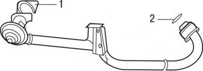
Pic. 4.3. EGR pipe: 1 - metal seal; 2 - sealing ring
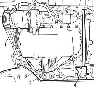
Pic. 4.42. Location of the air conditioning compressor in the engine compartment of the DW10TD engine: 1 - air conditioner compressor; 2 - jet bracket; 3 - shockproof amplifier of the sub-frame; 4 - chipper
Loosen the nut, remove the bolt and remove the reaction arm 2 (pic. 4.42) and 2 (pic. 4.3) engine mounts.
DW10ATED engine
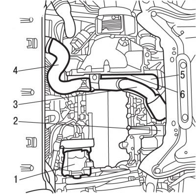
Pic. 4.43. Location of the compressor in the engine compartment with the DW10ATED engine: 1 - air conditioner compressor; 2 - jet bracket; 3 - air pipe at the outlet of the turbocharger; 4 - air cooler; 5 - bump stop of the shock-proof amplifier 6 - sub-frame
Remove air tube 4 (see fig. 4.43) to the air cooler.
Remove the air pipe 3 at the outlet of the turbocharger.
All engines
Remove anti-shock booster 3 (see fig. 4.42) subframe.
Remove bumper 4.
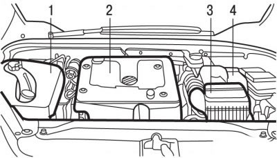
Pic. 4.44. Location of parts and assemblies in the engine compartment with the DW10TD engine: 1, 2 - decorative covers; 3 - air filter; 4 - battery
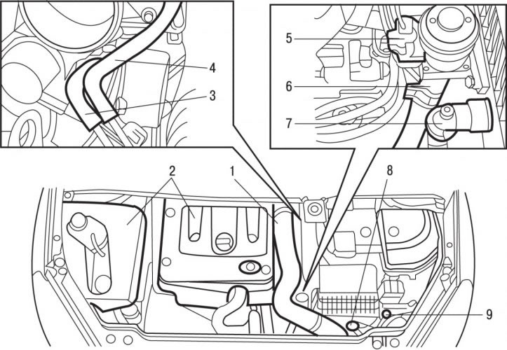
Pic. 4.45. Location of parts and assemblies in the engine compartment with the DW10ATED engine: 1 - air pipe at the outlet of the cooler; 2 - decorative covers; 3 - heater radiator pipe; 4 - hose of the vacuum brake booster; 5 - pin connector; 6, 7 - tubes; 8 - sensor; 9 - wiring harness
Remove decorative covers 1 and 2 (pic. 4.44), 3 (pic. 4.45).
Remove battery 4 (see fig. 4.43) and its bracket. Access to one of the bracket mounting bolts is possible through the left wheel arch.
Remove the air filter 3.
DW10ATED engine
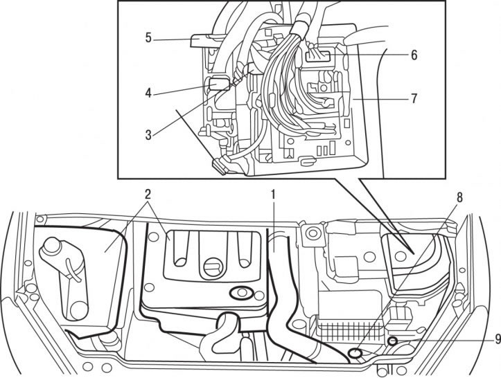
Pic. 4.46. Location of parts and assemblies in the engine compartment with the DW10ATED engine: 1 - air pipe at the outlet of the cooler; 2 - decorative covers; 3, 6, 7, 9 - wiring harnesses; 4, 5, 6, 7 - pin connectors; 8 - sensor
Disconnect and set aside harnesses 3, 6, 7, 9 (pic. 4.46), pins 4, 5, 6, 7 and sensor 8.
DW10TD engine
Disconnect the 32-pin electrical connector, gray, and the 48-pin electrical connector, brown, from the engine control unit.
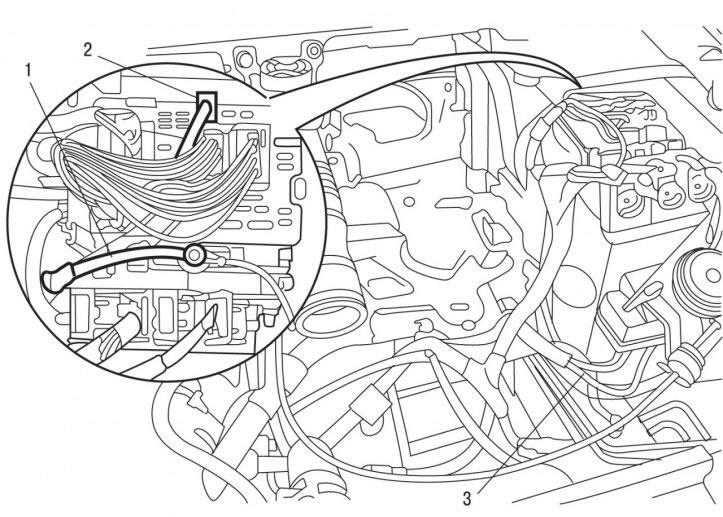
Pic. 4.47. Places of connection to the power unit of cables (1 and 3) and contact sockets (2)
Disconnect from the motor cable 1 and 3 (pic. 4.47) and pin 2, black.
All engines
If equipped, remove the headlight washers.
Remove the front bumper and headlights.
Remove the upper transverse front panel.
Remove the accelerator cable and accelerator pedal position sensor.
Remove the block of system of preheating.
Remove and set aside the hood latch.
Using the 0216-G1 10 mm and 0216-G2 13 mm joint release tools, release the shifter joints.
Disconnect and move aside the hose of the vacuum brake booster 4 (see fig. 4.45) and heater radiator hoses 3.
Disconnect the fuel supply and return pipes. To prevent dirt from entering the fuel system, close the ends of the pipes with suitable plugs.
Disconnect the radiator fan connector.
DW10ATED engine
Remove the engine air cooler.
All engines
Remove a radiator of system of cooling.
Remove the front panel.
Remove the bottom cross member of the front panel.
Remove the bolts and, without disconnecting the hoses, move aside and secure the air conditioning condenser.
Turn out the bolts and, without disconnecting the hoses, take aside and fix the compressor 1 (see fig. 4.42) air conditioning systems.
Attention! Do not open the cooling circuit of the air conditioning system.
Remove and, without disconnecting the hoses, take aside and secure the clutch slave cylinder.
Install a jack with a platform under the power unit and fix the engine to the platform through the supporting racks.
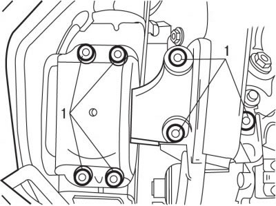
Pic. 4.21. Bolt location (1) right engine mount bracket (2)
Remove bolts 1 (see fig. 4.21) fasteners and remove the right engine mount.
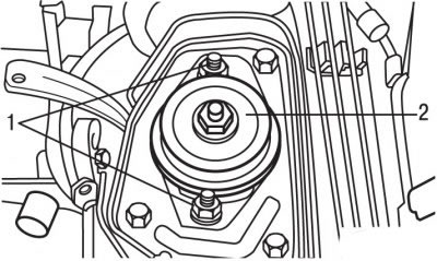
Pic. 3.53. Bolt location (1) and nuts (2) fixing the left intermediate support of the power unit
Remove bolts 1 (see fig. 3.53) and nut 2 fastening the left intermediate support of the power unit and remove the support.
Remove the elastic pad from the left support.
Using the 0317-AB gearbox mount pin remover, remove the left mount pin.
Make sure all wires, hoses, fittings and pipes are disconnected from the engine.
Remove the power unit, being careful not to hook on the surrounding elements.
If necessary, disconnect the gearbox from the engine.
Installation
Install the engine in the reverse order of removal, taking into account the following.
Replace with new self-locking nuts and bolts, which were tightened by additional turning to a certain angle, oil seals and gaskets, a clamp connecting the elements of the exhaust system, and turbocharger mounting nuts.
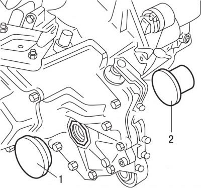
Pic. 3.7. Using mandrels (1 and 2) to replace differential seals
With mandrels 1 and 2 (see fig. 3.7) replace differential seals. Before installing the seals, fill the space between the seal lips with grease.
Install the power unit.
Install the right engine mount bracket and secure the bracket support with the bolts finger-tight at this point.
Tighten the right engine mount bracket bolts to 60 Nm.
Using the 0317-AB gearbox axle mandrel, install the left support axle with the washer and tighten it to 50 Nm.
Install the left support elastic pad.
By rocking the power unit from side to side, ensure the correct position on the supports.
Tighten bolts 1 (see fig. 3.53) fastening the left intermediate support of the power unit with a torque of 30 Nm, and nut 2 with a torque of 65 Nm.
Tighten the mounting bolts of the right engine mount bracket to 60 Nm.
Detach the support legs from the engine and lower the jack with the platform.
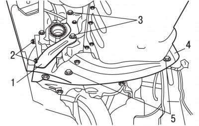
Pic. 4.48. Fastening of the shockproof amplifier of the underframe and bump stop: 1 - chipper; 2 - nuts, 40 Nm; 3 - bolts, 60 Nm; 4 - shockproof amplifier of the sub-frame; 5 - bolts, 40 Nm
Reinstall shock absorber 4 (pic. 4.48) subframe.
Tilt the power unit forward, install the bump stop 1.
Fasten the underframe reinforcement with bolts 5, tightening them to a torque of 40 Nm.
Tighten the bolts 3 of the lower mounting of the gearbox and the bump stop to 60 Nm.
Tighten nuts 2 to 40 Nm.
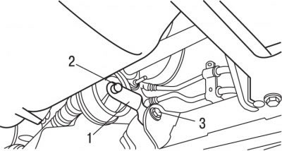
Pic. 4.49. Engine Reaction Arm Mount: 1 - jet lever; 2 - bolt, 55 Nm; 3 - bolt, 40 Nm
Install reaction arm 1 (pic. 4.49) engine mounts and secure with bolts, tightening bolt 2 to 55 Nm, and bolt 3 to 40 Nm.
DW10ATED engine
Install the catalytic converter and cross-tighten its fastening nuts to 25 Nm.
Install a particulate filter.
All engines
Install the air conditioning compressor and secure it with bolts.
Connect the wheel drives to the gearbox.
Further installation of the power unit is carried out in the reverse order of removal, taking into account the following.
Pour oil into the gearbox.
Fill the engine with oil.
Install the front wheels and secure them with bolts, tightening them to a torque of 90 Nm.
Fill with coolant and bleed air from it.
Connect the battery.
Fill the fuel system with fuel and bleed air from it.
Carry out the operation of programming the computer of the engine management system.
