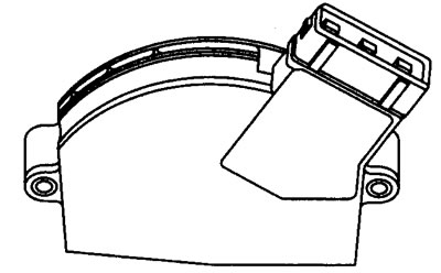
12.16 Throttle position sensor (TPS)
Throttle position sensor voltage and resistance values
Terminal numbers

* Throttle position sensor resistance values are not set for the MM8P system. However, the resistance between the respective terminals should change smoothly as the throttle valve opens and closes.
See illustration 12.11
Influence of external factors
- Too tight fastening screws
- Loose throttle position sensor multi-pin connector
- Poorly adjusted or stuck throttle
- Poorly adjusted or stuck throttle cable
TPS sensor adjustment
If a malfunction is detected or if the voltage and resistance values are out of specification, the throttle position sensor must be replaced.
Throttle position sensor test (TPS) (general check)
1. Inspect the throttle position sensor multi-pin connector for signs of corrosion or damage.
2. Make sure the connector terminal pins are properly installed and making good contact with the throttle position sensor multi-pin connector.
3. Any of the above malfunctions result from a weak or intermittent signal from the throttle position sensor.
Testing the TPS Sensor with an Oscilloscope or Voltmeter
1. Peel back the rubber insulation (where possible) to the throttle position sensor multi-pin connector OR connect an output block (WWII) between the multi-pin connector of the electronic control unit and the electronic control unit.
2. Connect the negative lead of an oscilloscope or voltmeter to ground on the engine OR to the ground terminal #1 of the throttle position sensor.
3. Connect the positive probe of an oscilloscope or voltmeter to the wire attached to terminal #3 of the throttle position sensor.
4. Throttle closed, ignition on.
5. Compare the voltage value at closed throttle with the value specified in the specifications.
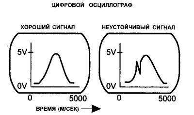
6. Open and close the throttle a few times and check for a gradual increase in voltage to more than 4.25-4.95 volts. If the signal is unstable, then proceed to the test described below, titled «The output signal is unstable».
7. If a digital voltmeter is used, it is important that it can perform the function of a plotter.
8. If the oscilloscope timebase is approximately 5 seconds, the screen may display «curve» throttle position sensor output diagram as throttle opens and then closes (see illustration 12.15).

12.15 Typical Manifold Air Pressure Sensor/Throttle Position Sensor Output Waveform (MAP/TPS)
9. If there is no throttle position sensor signal voltage, then proceed to the test described below, titled «No signal voltage»
Intermittent output
1. An unstable output occurs when the output voltage steps or drops to zero, or an open circuit occurs.
2. Check the resistance of the throttle position sensor at different terminals.
3. If the output signal of the throttle position sensor is unstable, then the potentiometer is most likely defective. In this case, the only way out is to replace the throttle position sensor with a new one.
The signal voltage or supply voltage matches the battery voltage
Check for a short in the wire connected to the positive terminal (+) battery, or sensor supply voltage.
No signal voltage
- Check reference voltage supply (5.0 V) at terminal #2 of the throttle position sensor.
- Check the effectiveness of the ground at terminal No. 1 If the supply and ground parts of the circuit are good, check for continuity in the signal wire between the throttle position sensor and the electronic control unit.
- If there is no power supply and/or ground, check for continuity in the power wire and/or ground wire between the throttle position sensor and the ECU.
- If the throttle position sensor wiring is OK, check all power and ground contacts of the electronic control unit. If these contacts are in working condition, then the electronic control unit may be faulty.
