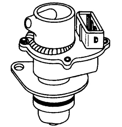
12.17 Vehicle speed sensor (VSS)
Approximately 12 volts is supplied to the vehicle speed sensor from the ignition switch in the on position. As the speedometer cable rotates, the Hall effect sensor turns on and off alternately to send a square wave signal to the ECU. signal frequency (8 pulses per revolution) determines the speed of the car.
Vehicle speed sensor voltage values (VSS)
Terminal numbers

See illustration 12.11
Vehicle speed sensor frequency (VSS)
8 pulses per revolution of the speedometer drive cable.
Checking the vehicle speed sensor (VSS) (general check)
1. Inspect the vehicle speed sensor multi-pin connector for signs of corrosion or damage.
2. Make sure the connector terminal pins are properly installed and making good contact with the vehicle speed sensor connector.
Checking the performance of the vehicle speed sensor (VSS)
1. Checking is quite simple. The sensor has three wires: a power wire, a ground wire and a signal wire.
2. Connect the positive voltmeter lead to the vehicle speed sensor multi-pin connector (see note 2) or connect output unit (WWII) between the multi-pin connector of the electronic control unit and the electronic control unit.
3. Connect the negative lead of an oscilloscope, breaker closed time meter, or voltmeter to ground on the motor.
4. Connect the positive probe of an oscilloscope, breaker closed duration meter, or voltmeter to the appropriate terminal of the vehicle speed sensor signal wire.
Checking the signal from the vehicle speed sensor (VSS)
Note. The supply voltage can be generated from the ignition switch or relay. If voltage is supplied from a relay, the connection may be from the first or second contact of the relay. The first relay contact supplies voltage when the ignition is on, the second contact of the relay supplies voltage only when the engine is running.
1. Turn on the ignition or start the engine.
2. The signal is sent by the sensor when the drive wheels rotate. Wheel rotation can be achieved in one of the following two ways:
3. Push the car forward.
4. Place the vehicle on an incline so that the drive wheels can rotate freely. Either spin the wheels by hand or start the engine at low speed.
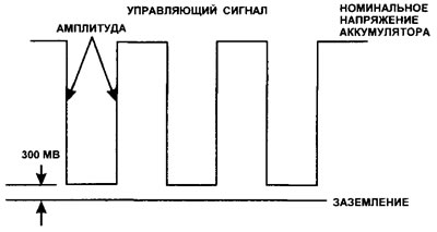
5. The instrument must reflect the waveform, duty cycle or voltage (see illustration 12.18).

12.18 Typical vehicle speed sensor output waveform (VSS)
No signal or signal unstable, duty cycle or voltage
1. Vehicle speed sensor multi connector disconnected, ignition on.
2. Check the voltage supply to the vehicle speed sensor power wire terminal.
3. No voltage: Check the power supply from the ignition switch or relay, depending on the design of the system.
4. Check for grounding at the vehicle speed sensor ground wire terminal.
5. Disconnect the vehicle speed sensor multi-pin connector.
6. Connect the positive voltmeter lead to the signal wire terminal.
7. The device should indicate the voltage within 8.5 and 10.0 Volts.
The voltage in the ground and power wires is within the normal range
- The vehicle speed sensor may be defective, or it is not being rotated by the speedometer drive (those. broken cable or faulty gearbox).
No signal voltage
1. Check the voltage at the terminal of the multi-pin connector of the electronic control unit.
2. If the voltage of the electronic control unit is within normal limits, check for continuity in the signal wire.
3. If there is no voltage on the contact of the electronic control unit, then check the supply and ground contacts of the unit. If the contacts are in working condition, then the electronic control unit may be faulty.
