It should not be forgotten that before disassembling the engine, all removed parts must be marked accordingly, so that they can then be installed properly if they are to be reinstalled. This applies in particular to pistons, valves, bearing caps and bearing shells. When removing these parts, stack them in such a way that they are not mixed up.
Do not mark or write on bearing cap or sealing surfaces with a scriber or sharp object. To do this, there is paint or a felt-tip pen. The valves can be installed in a cardboard box by punching holes in the bottom of the box and marking each valve with the appropriate number (see illustration 3.0).
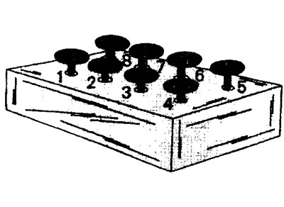 3.0 Place the removed valves in the carton
Many parts are made of aluminum and must be handled properly. If a hammer is needed to separate them, then use rubber, plastic or leather.
If a suitable mounting stand is not available, use trestle jacks, positioning them so as to provide access to the engine from both above and below.
Cylinder head - removal and installation
Removing the cylinder head is not particularly difficult. However, after the head is in place, you will need a special measuring device to properly tension the toothed belt. If such a device is not available, then the tension of the toothed belt must be checked and recorded before removing the cylinder head. To do this, press the index finger of the hand on the toothed belt and at the same time measure the amount of deflection. After installing the cylinder head, the toothed belt can be installed with the same tension as it was before removal.
In order to fix the crankshaft and camshafts in a certain position and prevent the engine from turning, you will need stop bolts (see illustration 3.0a).
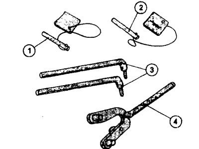
3.0a Tools required for removing and installing the cylinder head
1 - thrust bolt for fixing the camshaft
2 - thrust bolt for fixing the crankshaft
3 - levers for removing and installing the cylinder head
4 - counter support for the camshaft drive gear
You can use suitable bolts with a diameter of 8 or 10 mm. In addition, the diameter of the holes for fixing the shafts is not the same for all engines.
In general, to remove the cylinder head, do the following.
1. Jack up the right side of the vehicle to provide access to the wheel arch.
2. Disconnect the battery. Lay the wires with terminals so that they do not cause a short circuit of the battery in case of unbending.
Attention! Disconnecting the battery will delete the security code in the radio. For this reason, before disconnecting the battery, make sure that the security code is written down so that it can be entered after the battery is connected.
3. Drain the coolant. The best way to do this is to disconnect the lower radiator hose. Collect the coolant in a separate container, especially if it is normal.
4. Remove the accessory drive belt.
5. Turn out bolts of fastening of a forward wheel and a mudguard.
6. Turn out spark plugs to facilitate cranking of the engine.
7. Designate and disconnect from a head of the block of cylinders all hoses, pipelines and wires connecting a head and a body or a head and the block of cylinders.
8. Remove the air filter and a broad tank of a cooling liquid. On vehicles with an engine with two camshafts and 16 valves, the air filter is located on the right side of the engine compartment (see illustration).
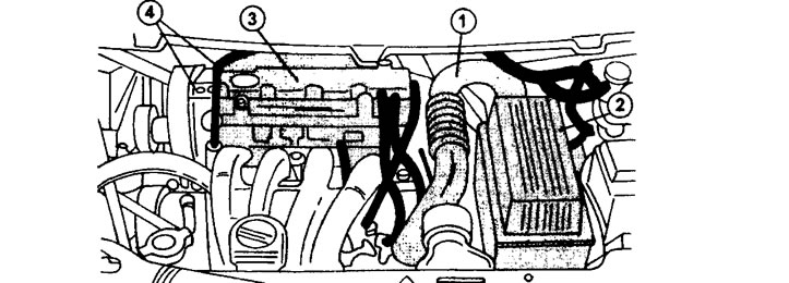
3.8 Engine compartment of a vehicle with a 16 valve DOHC engine
1 - air intake hose
2 - air filter
3 - ignition coil
4 - cylinder head cover
9. Disconnect the exhaust pipe mufflers from the exhaust manifold
Turbocharged engines
10. Disconnect hoses 1 and 2, lines 3 and 4 and heat deflector 5 (see illustration).
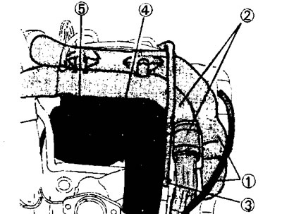
3.10 Disconnect hoses 1 and 2, pipes 3 and 4 and heat deflector 5
11. Turn away four nuts of fastening of a turbocharger to a final collector. Plug the intake and exhaust ports of the turbocharger with a suitable material to prevent dirt from getting in.
12. Release the wiring harnesses, pipelines, wires, etc. fixed to the appropriate holders on the intake manifold. and take them away from the collector.
13. Disconnect an inlet collector and wring out it from a head of the block of cylinders. Plug holes with suitable material.
8 valve engines
14. Turn the crankshaft until the camshaft is as shown in (illustrations 3.14.)
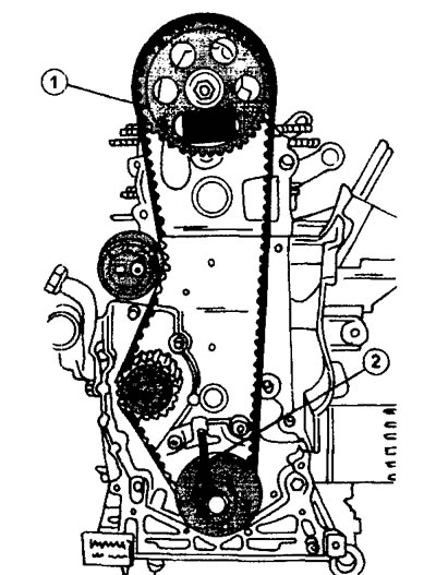
3.14 Camshaft and crankshaft drive gears with 8 valves
1 - hole in the camshaft gear for the thrust bolt
2 - hole in the crankshaft gear for the thrust bolt
Lock the camshaft in this position by inserting a stop bolt into the hole on the camshaft gear and into the hole on the block head. The crankshaft gear is fixed in a similar way. Thrust bolts for the camshaft and for the crankshaft are different from each other. The thrust bolts for the camshaft gear used by Citroen auto repair shops are 7004T or 7014T, and the crankshaft bolts are 7014T.N.
16 valve engines
Fixing the camshafts and crankshafts for these engines is carried out in the same way as for engines with 8 valves, however, in this case, the engine must be rotated until both camshafts and the crankshaft are in the appropriate position (see illustration 3.06)
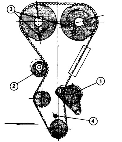
3.06 Gears for driving camshafts and crankshafts of a 16-valve engine
1 - belt tensioner roller
2 - tension roller
3 - hole in the gears of the camshafts for the thrust bolt
4 - thrust bolt of the camshaft gear
15. Remove a gear belt.
16. Turn out for several passes all 10 bolts of fastening of a head of the block of cylinders, acting in return sequence of a tightening of bolts (see illustration).
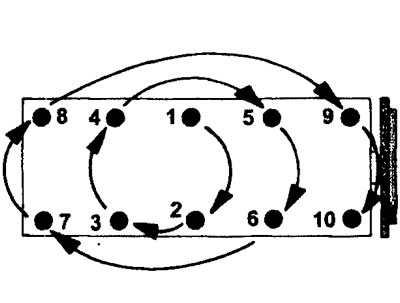
3.16 Cylinder head bolt tightening sequence
17. Remove the cylinder head. If a hoist or an identical lifting device is available, it is sufficient to attach the hooks or ropes to the eyelets on the head and remove it. In workshops, to remove the cylinder head, use pry bars with ends bent at an angle of 90° (see illustration 3.0a). If necessary, such mounts can be made independently. The ends of the mounts bent at an angle of 90°are inserted into the holes for the bolts securing the head to the cylinder block and the head is removed (see illustration 3.17).
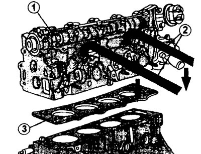
3.17 Removal and installation of the cylinder head with pry bars with 90°bent ends 1 - cylinder head
2 - mounts with 90°angled ends
3 - cylinder head gasket
The head is preliminarily swung from side to side to loosen its fit on the cylinder block.
18. Remove the cylinder head gasket.
16 valve engine
19. Loosen the bolts of both cylinder heads in several passes, acting from the outside to the center and loosening the bolts evenly and remove the heads.
20. Release from fastenings a plait of wires of atomizers and disconnect wires.
21. Move the fuel distribution line to the side without disconnecting the fuel lines (see illustration).
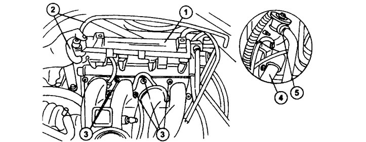
3.21 Move the fuel distribution line to the side without disconnecting the fuel lines.
3 - intake manifold nuts
4 and 5 - hose fastening
22. Turn away nuts of fastening of an inlet collector and disconnect it together with the throttle body.
23. Turn away fastening of hoses and remove hoses.
24. Secure the press-fit cylinder liners with holders to prevent them from moving (see illustration).
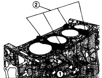
3.24 Secure the press-fit cylinder liners with holders to prevent them from moving
The cylinder head is installed in the reverse order of removal. To carry out work on installing the cylinder head, a Torx 55 socket wrench with a replaceable socket head is required, as well as a goniometer for correctly tightening the bolts.
2.0 liter engine, 8 valves (XU10J2 and XU10J2/TE)
25. Measure the length of the cylinder head bolts. The bolt shank is measured from the underside of the bolt head to the end of the shank. Bolts longer than 124.5 mm must be replaced.
26. Install a new cylinder head gasket. The gasket must match the type of engine. The gasket is installed dry, without lubrication. Before installing the gasket, make sure both dowel pins are in place at the corners of the cylinder head. ledge (uvula) The cylinder head gasket must face the flywheel.
27. Grease a carving of bolts of fastening of a head of the block of cylinders, and also the bottom part of a head of bolts.
28. Reinstall the cylinder head. The camshaft gear must remain fixed when installing the head. If the stop bolt with which the camshaft gears were fixed before removing the cylinder head was removed during the work, then the gear should be fixed again before installing the cylinder head (see illustration).
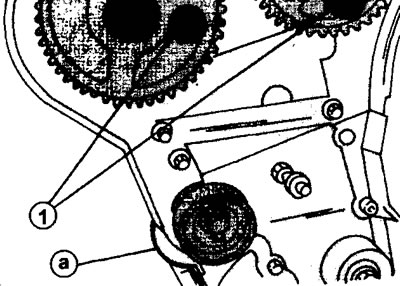
3.28 Thrust bolts 1 of the camshaft gears. Fasten the protective cover on the belt as shown in the illustration
29. Establish fastening bolts in openings of a head of the block of cylinders and screw them by hand.
30. Tighten the fastening bolts with a torque of 35 Nm, acting from the middle of the head to its ends according to the numbering of the bolts (see illustration 3.16). When tightening, use only a Torx socket wrench to avoid damaging the bolt head.
31. Tighten the bolts with a torque of 70 Nm in the sequence shown in illustration 3.16.
32. Tighten the bolts 160°following the tightening sequence. If you have a goniometer at your disposal, then the procedure for turning the bolts is not difficult. The required angle of adjustment is reached as soon as the wire pointer on the goniometer is at the desired degree (see illustration).
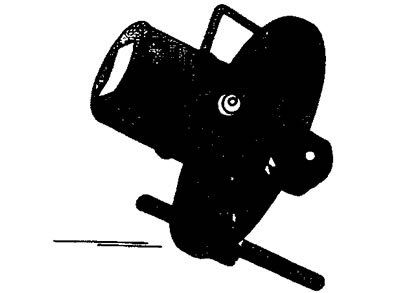
3.32 Protractor used to tighten bolts to a specified angle
If there is no goniometer at your disposal, then you can be guided by the rule that half a turn is equal to 180°. You can designate an angle of 90°, which can be divided into 6 equal sectors. Each sector will be equal to 15°. To get an angle of 160°, the rotation is not performed by 180°, but minus a little more than 15°. Further tightening of the bolts is not required.
33. Establish a gear belt, and also all details which were disconnected before removal of a head of the block of cylinders.
16 valve engine
34. Measure the length of the cylinder head bolts. The bolt shank is measured from the underside of the bolt head to the end of the shank. Bolts longer than 112 mm must be replaced.
35. Install a new cylinder head gasket. The gasket must match the type of engine. The gasket is installed dry, without lubrication. Before installing the gasket, make sure both dowel pins are in place at the corners of the cylinder head. ledge (uvula) The cylinder head gasket must face the flywheel.
36. Grease a carving of bolts of fastening of a head of the block of cylinders, and also the bottom part of a head of bolts.
37. Reinstall the cylinder head. The camshaft gear must remain fixed when installing the head. If the stop bolt with which the camshaft gear was fixed before removing the cylinder head was removed during the work, then the gear should be fixed again before installing the cylinder head.
38. Establish fastening bolts in openings of a head of the block of cylinders.
39. Tighten the fastening bolts with a torque of 35 Nm, acting from the middle of the head to its ends according to the numbering of the bolts.
40. When tightening, use only a Tox socket wrench so as not to damage the bolt head (see illustration).
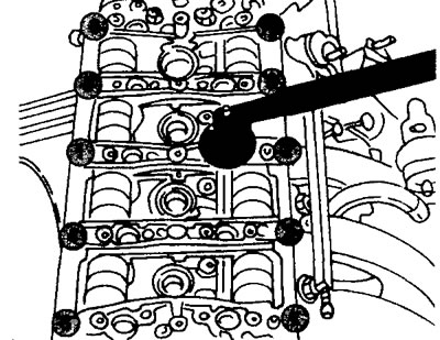
3.40 Tighten the 16-valve engine cylinder head bolts with a Tox socket wrench. The illustration also shows the use of a goniometer to turn the bolts 160°
41. Tighten the bolts with a torque of 70 Nm as shown in illustration 3.40.
42. Tighten the bolts 160°following the tightening sequence. The required angle of adjustment is reached as soon as the wire pointer on the goniometer is at the desired degree (see illustration 3.40). Further tightening of the bolts is not required.
43. Establish a gear belt, and also all details which were disconnected before removal of a head of the block of cylinders.
44. Tighten, in sequence, the cylinder head cover bolts. To avoid deformation of the cover, the bolts must be tightened in the following sequence (see illustration).
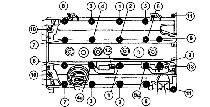
3.44 Bolt sequence for both cylinder head covers on a 16-valve engine.
45. Screw in all bolts from I to 11 with the moment of 13 Nm.
46. Tighten bolts 4a and 5a with a torque of 2 Nm.
47. Tighten bolts 12 and 13 with a torque of 15 Nm.
48. Install the ignition coil and secure it with a tightening torque of 10 Nm.
49. Fix on a head of the block of cylinders all pipelines, wires and plaits of wires.
50. Bolt the muffler downpipe to the exhaust manifold.
51. Fix on a head of the block of cylinders a distributive fuel line together with atomizers.
XU7 engine (1.8 l)
52. Remove the cylinder liner holders.
53. Clean the sealing surfaces of the cylinder head and block, removing the remnants of the old seal with an appropriate cleaner.
Attention! Do not clean the sealing surfaces of the head and cylinder block with a hard scraper or sanding paper.
54. Measure the protrusion of the cylinder liners, if necessary.
Installing the cylinder head is as follows.
55. Install a new cylinder head gasket. The gasket must match the type of engine. The gasket is installed dry, without lubrication. Gaskets of regular or repair sizes are available for sale.
56. Measure the length of the cylinder head bolts. The bolt shank is measured from the underside of the bolt head to the end of the shank. Bolts longer than 176.5 mm must be replaced.
57. Grease a carving of bolts of fastening of a head of the block of cylinders, and also the bottom part of a head of bolts and put on washers on bolts.
58. Reinstall the cylinder head and screw all 10 mounting bolts into the cylinder head holes by hand. Screw in the bolts, acting from the middle to the outside.
59. Tighten the mounting bolts with a torque of 60 Nm, acting from the middle of the head to the outside according to the numbering of the bolts. When tightening, use only a Torx socket wrench to avoid damaging the bolt head (see illustration 3.16).
60. Loosen all bolts in the reverse order of tightening.
61. Tighten the bolts again, following the diagram shown in (illustrations 3.16.) The tightening torque is 20 Nm.
62. Tighten all bolts to 300°using a protractor (see illustration 3.32). If there is no protractor, then it is recommended to proceed from the fact that the angle of 270°represents 3/4 turn of the key. You can designate an angle of 90°and break it into 6 equal sectors. The two sectors give a total of 30°, which will need to be added to make a 300°turn.
After the specified tightening, the cylinder head bolts do not need to be tightened any further, even on a warm engine.
63. Install the toothed belt, as well as all the parts that were removed before dismantling the cylinder head.
