All pistons have two compression rings and one oil scraper ring. The top compression ring has chrome-plated working edges. Second compression ring scraper type, trapezoidal section. Piston rings are numbered, which must face up when installing the rings.
This manual gives a general description for all pistons and their parts, although they differ from one engine to another. If the engine does not have insert sleeves, then the mention of them in the text does not apply to these engines.
Attention! When ordering new pistons (and shells) be sure to include the engine number.
Disassembly
Special tools are required to separate pistons and connecting rods. If these are not available, then this work should be entrusted to the workshop. Even when replacing pistons, these special tools are necessary, for example when installing piston pins. An appropriate hotplate is also required, with which the connecting rod head is heated to a temperature of 250°C. To check the heating temperature of the connecting rod head, you need a fusible pin that melts at exactly this temperature. Based on the foregoing, we recommend that the disassembly and replacement of pistons and connecting rods be entrusted to a workshop, dismantling them independently for delivery to the workshop.
1. Remove pistons and connecting rods from cylinder liners or cylinder bores. Apply the appropriate marks so as not to confuse the parts in places.
If it is only necessary to replace the piston rings, then the old rings must be removed in order using piston ring pliers (see illustration 10.1).
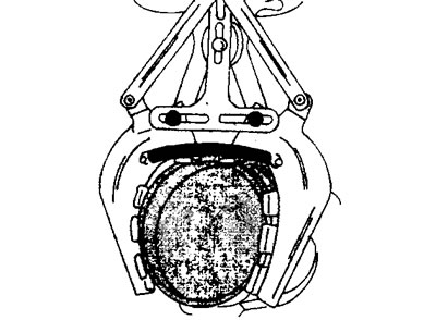
10.1 Removing piston rings with ring pliers
If the same rings are re-installed, they should also be marked in order to put them in their original places.
In the absence of pliers for installing piston rings, the latter are removed by placing metal plates under both ends of the rings.
For further disassembly of the piston, a special tool is also needed. The piston pin can be pressed out with a striker by placing the piston in a special press (see illustration 10.1a).
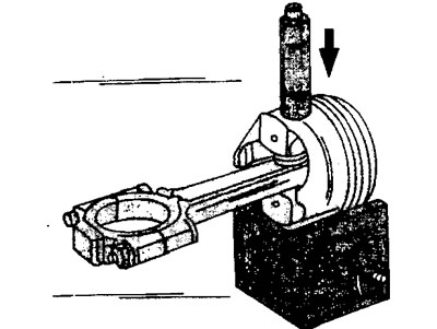
10.1a Pressing out the piston pin on a special press (mandrel). The hole in the press must be aligned with the hole in the piston
If the piston is separated from the connecting rod, then this piston cannot be reinstalled, because when the pin is pressed out, the bore size is violated.
Examination
Carefully inspect all details. If their surfaces show signs of corrosion, scratches, or their wear has reached acceptable limits, then such parts must be replaced.
2. Measure the clearances of the piston rings in height in the grooves by inserting the rings one by one into the corresponding groove on the piston. The size of the gap is determined using a template inserted into the gap between the working edge of the ring and the surface of the groove on the piston. If the clearance is not within specification, either the rings or pistons are worn (see illustration).
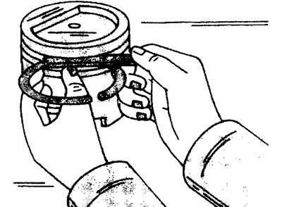
10.2 Measurement of the piston ring clearance in height. Thoroughly clean the ring grooves on the piston before measuring
3. Measure backlashes in locks of piston rings. To do this, insert the rings in order into the cylinder liner. With the piston upside down, push the ring into the sleeve about 15 mm from the bottom edge of the sleeve. To determine the position of the ring in the liner, lay the cylinder block on its side (see illustration).
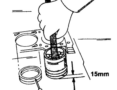
10.3 Measure the gaps in the locks of the piston rings. To do this, insert the rings in order into the cylinder liner. With the piston upside down, push the ring into the sleeve about 15 mm from the bottom edge of the sleeve.
To measure the gap of the ring lock, insert a measuring template into the hole between the ends of the ring. The gaps of the locks are not adjustable and, with increased gaps, the rings must be replaced.
4. Measure the piston diameter with a micrometer in a plane perpendicular to the piston pin. According to the diameter of the hole for the piston pin, pistons are divided into three classes. For this reason, piston pins are marked with paint of the corresponding color on the end face. Pistons and piston pins are produced in pairs and branded accordingly.
On the bottom of the pistons of engines with plug-in working cylinder liners, a letter is applied, and notches on the cylinder liners. The pistons are also coated with paint, which marks the piston pins installed on this class of pistons.
To check the clearance between the piston and the cylinder, measure the diameter of the cylinder bore. The bore is measured longitudinally and transversely and at three points along the entire height of the cylinder liner or bore. In this way, the maximum and minimum diameters are determined. Write down the obtained values.
5. Subtract the piston diameter from the liner or cylinder bore diameter. The resulting difference will be the gap between the piston and the sleeve (wall) cylinder holes. If the clearance is higher than the nominal values, then it is necessary to install a new set of pistons (and cylinder liners). Instead, pistons are installed with the same markings as the previous ones. Sometimes, in order to read the letter marking, it is necessary to remove carbon deposits from the piston crown.
6. Check the condition of the piston pins and pin holes and make sure they are not worn or damaged. Piston pins are only supplied complete with pistons. The piston pin must have a certain clearance. This means that it should fit into the hole in the piston with a simple push of the thumb, but should not fall out.
Assembly
After checking and necessary replacement of the parts of the connecting rod and piston group, the pistons and connecting rods are assembled.
7. Make sure the connecting rods are not twisted or bent. To do this, check the connecting rod in the appropriate setting. We recommend that this test be carried out in a workshop. Twisted or bent connecting rods will adversely affect engine performance.
8. Place the cranks on a hot plate to warm them up. Position the connecting rods on a star-shaped plate so that only the connecting rod heads are heated (see illustration).
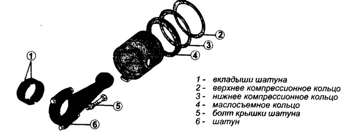
10.0 Elements of the connecting rod and piston group
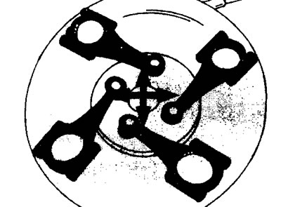
10.8 Place the connecting rods on the stove to warm them up. Position the connecting rods on a star-shaped plate so that only the connecting rod heads are heated
Using a fusible pin, check the heating temperature of the connecting rod heads, which should not be higher than 25°C. The caps of heated connecting rods must be tightened with bolts so that there is a gap of at least 1 mm between their halves.
9. Prepare the piston pin for assembly by sliding it over the piston pin roller and fasten it with the screw. Do not tighten the screw tightly so that jamming does not occur when the finger expands from contact with the heated connecting rod. Lubricate the roller and piston pin well with engine oil.
If, after assembling the pistons and connecting rods, new connecting rod bearings are installed, then the connecting rods can be installed without adhering to the markings made during removal.
The piston and connecting rod must be assembled with the arrow on the piston head facing the front of the engine. In addition, there is a designation on the piston crown «DT», indicating that the arrow should point towards the toothed belt (see illustration).
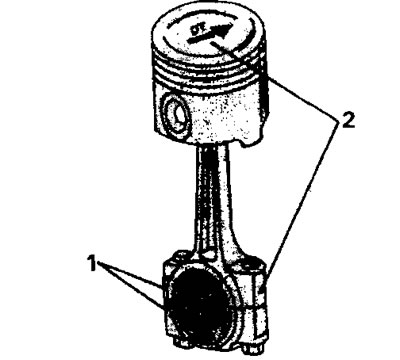
10.9 Proper assembly of piston and connecting rod. Marks on the connecting rod and connecting rod cap (1), as well as the inscription «DT» and notch (2) should be in the position as shown in the illustration. Piston pins on 16 valve engines are held in place by circlips
10. Mount the piston in the special tool so that the hole in the piston matches the hole in the special tool.
11. Grab the heated connecting rod with pliers and insert it into the piston fixed in the special tool.
12. Push the piston pin, previously attached to the roller, into the piston hole to the shoulder on the roller and hold it in this position until the connecting rod cools (see illustration).
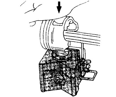
10.12 Push the piston pin, pre-mounted on the roller, into the piston hole to the shoulder on the roller and hold it in this position until the connecting rod cools down
When pushing the pin into the hole, check the alignment of the holes in the connecting rod head and in the piston so that the pin is positioned correctly. Move the connecting rod if necessary to maintain alignment.
To properly connect the pin to the connecting rod, press the pin in as soon as possible, as the connecting rod cools quickly and after cooling it will not be possible to change the position of the pin.
A few seconds after the piston pin is pressed in, release the piston from its mounting in the tool and check that the piston will move freely on the connecting rod after the connecting rod has cooled.
13. Turn out the shaft of the adaptation for installation of a piston pin and in the same way connect the following piston and a rod. After the connecting rod has cooled, lubricate the pin with engine oil through the holes in the piston bosses.
14. Install the piston rings in order on the piston. Label «TOR» on both compression rings must point upwards. Before installation, carefully inspect the rings so as not to confuse them. Tongs are required to set the gauge. In their absence, thin metal plates can be installed along the outer diameter of the piston (e.g. measuring templates) and fix the rings by putting them on these plates. Remove the plates as soon as the ring is at the level of the corresponding groove. Be careful because the rings are fragile and break easily.
15. Lubricate the piston rings with engine oil and install them on the piston so that their locks are located properly.
16. Install the oil scraper ring lock on the piston as shown in (illustrations 10.16),
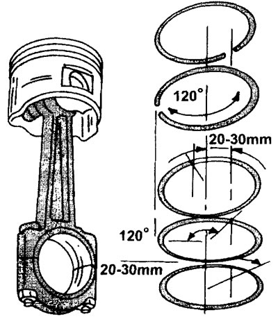
10.16 Location of piston rings on the piston
and shift both compression rings by 20-30 mm so that their locks are located at an angle of 120°relative to the oil scraper ring lock (see illustration 10.17a).
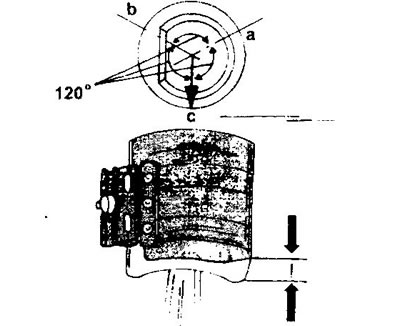
10.17a Engine piston XU10. The mounting sleeve for installing these pistons in the cylinder bores must be mounted so that the lower part of the piston skirt protrudes from under the sleeve (see arrows), a, b, c - the location of the locks of the piston rings on the piston
17. Lubricate the pistons with engine oil and insert them into the appropriate cylinder liners or bores in the cylinder block. A mounting sleeve is required to install the pistons and compress the piston rings. If the pistons are installed in working cylinder liners, then the mounting sleeve is fixed on the piston so that the top of the piston protrudes from under the sleeve by 4-5 mm (see illustration).
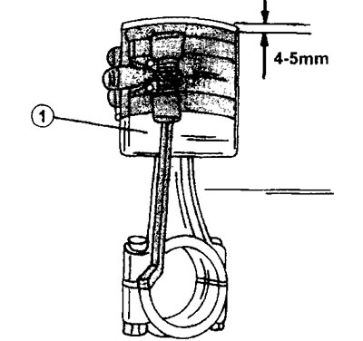
10.17 Attaching the mounting sleeve to the piston inserted into the cylinder liner
The sleeve fixed in this way allows the piston to be installed from below the cylinder liner. When installing pistons in cylinder bores, the mounting sleeve must be mounted differently. In this case, the sleeve must be located on the piston so that the lower part of the piston skirt protrudes (see illustration 10.17a). After that, insert the piston from above into the cylinder bore in the cylinder block (see illustration 10.17b).
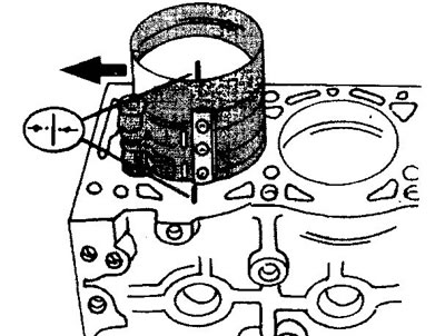
10.17b Installing the piston with a mounting sleeve in the cylinder bore in the cylinder block. Make sure that the marks on the pistons and cylinder bores match
Make sure that the marks on the pistons and cylinder bores match.
18. After installing the pistons in the cylinder liners, check the position of the pistons in them and make sure that the flat side of the connecting rod is parallel to the plane on the outer surface of the sleeve, and the arrow on the piston bottom points towards the timing belt (see illustration).
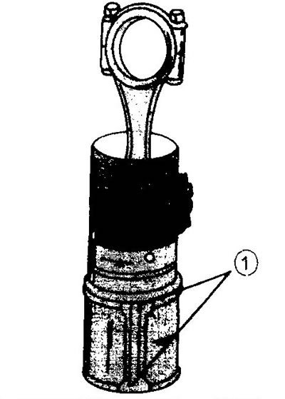
10.18 Install the pistons and connecting rods in the cylinder liners so that the flat side of the connecting rod is parallel to plane 1 on the outer surface of the sleeve
19. Install, if required, new O-rings in the base of the sleeves.
20. Insert the liners into the cylinder block, not allowing them to move and measuring the protrusion of the liners (see relevant chapter).
21. Make sure that the marks on the top of the sleeves line up with the marks on the cylinder head and that the arrows on the bottoms of the cylinders point towards the timing belt (see illustration 10.17b).
22. Install the connecting rod bearing caps. Tighten the bearing fastening nuts first with a torque of 40 Nm, and then unscrew and tighten again, but with a torque of 20 Nm. After that, tighten all nuts using a goniometer by 70°.
23. Make sure that the marks on the connecting rods and on the bearing caps are on the same side.
After tightening all the bearing caps, rotate the crankshaft several times to make sure that it rotates freely and does not wedge anywhere.
