Note. The front hub bearings use sealed double row roller bearings, pre-adjusted and pre-lubricated. The resource and characteristics of the bearings are designed for the entire life of the vehicle, and therefore the bearings do not require any additional maintenance or attention. Never over tighten the axle shaft bolt when attempting to adjust a bearing.
Note. A hydraulic press is required to disassemble and assemble the assembly. If not available, a large bench vise and spacers may be adequate replacements (e.g. large sockets).The bearing inner races are press fit on the hub. If the inner ring remains on the hub after it is pressed out of the steering knuckle, a special puller will be required to remove it. At installation it is necessary to use a new lock ring of fastening of the bearing.
1. Remove the steering knuckle assembly as described in paragraph 2.
2. Place the steering knuckle on sturdy wooden blocks and make sure it is stable. Alternatively, secure the steering knuckle in a vise. Using a tubular mandrel that only rests against the inner end of the hub, press the hub out of the bearing. If the inner race of the outer row of the bearing remains on the hub, remove it. using a bearing puller (see note above).
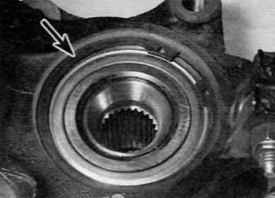
3. Remove the bearing circlip from the groove on the inside of the steering knuckle (pic. 3.3).

Pic. 3.3. Retaining ring for fixing the front hub bearing (marked with an arrow)
4. If necessary, install the inner race back into position relative to the bearing cage. Place the steering knuckle on a secure support with the inner side down. Using a arbor that only rests against the inner race, press the bearing assembly out of the steering knuckle.
5. Thoroughly clean the hub and steering knuckle, removing all traces of dirt and grease, and clean up any bumps or burrs that may interfere with assembly. Check both elements for cracks or any other signs of wear or damage and replace if necessary. Replace the retaining ring, regardless of its apparent condition.
6. When reassembling, apply a thin coat of oil to the bearing outer race and knuckle bore surface to facilitate bearing installation.
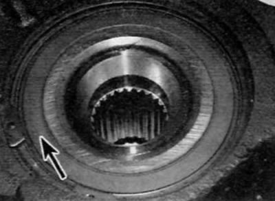
7. Position the steering knuckle on a secure support and install the bearing in the steering knuckle. Fully press in the bearing. Do not misalign the bearing during installation. Use a tubular mandrel that only abuts against the outer ring of the bearing. Please note that on models from September 2002 equipped with ABS, an impulse wheel is located on the inner edge of the bearing, which is an integral part of the bearing. When installing the bearing, make sure that this end is inboard next to the wheel speed sensor for the ABS system (pic. 3.7). Take care not to damage the impulse wheel and do not place it near a magnetic field source. Take care of the cleanliness of the impulse wheel.

Pic. 3.7. On later models, be careful not to damage the bearing seal (marked with an arrow); It has a built-in wheel speed sensor pulse wheel
8. With the bearing correctly positioned, secure it with a new circlip. which must be properly inserted into the groove in the steering knuckle. Note. On September 2002 and later models equipped with ABS, align the gap between the ends of the snap ring lock with the gap for the ABS wheel sensor.
9. Position the wheel hub on a secure support with the outer edge down and fit the inner race of the steering knuckle bearing onto the end of the hub. Press the bearing onto the hub using a tubular mandrel, which rests only on the inner ring of the hub bearing, until the ring rests against the collar on the hub. Check that the hub can rotate freely and wipe off any excess oil or grease.
10. Install the steering knuckle assembly as described in paragraph 2.
