Fuses
1. Fuses are designed to break an electrical circuit when a predetermined amperage is reached to protect components and wiring that could be damaged by too much current. Any increase in current will be the result of a fault in the electrical circuit, usually the result of a short circuit (see paragraph 2).
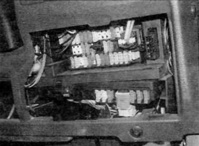
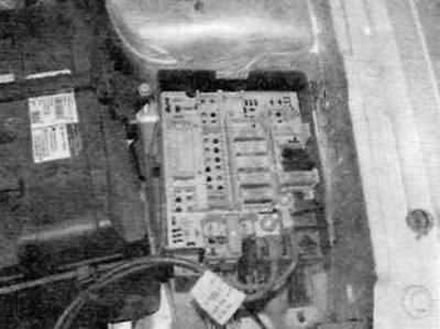
2. Most fuses are located in the front fuse box on the driver's side behind a removable cover. Additional fuses (including larger, higher current fuses of type «maxi») located in the fuse/relay box on the left side of the engine compartment (pic. 3.2, a, b).

Pic. 3.2, a. Most of the fuses are located in the front panel fuse box...

Pic. 3.2b....and in the engine compartment fuse/relay box
3. To access the front panel fuses, remove the bottom section of the front panel (turn the latches 90°and remove the panel). To access the fuses in the engine compartment, simply remove the cover from the fuse/relay box. The main fuses and relays are in the top section of the box, and the fuses are type «maxi» located below.
4. To remove the fuse, first disconnect the electrical circuit in question (or turn off the ignition), then remove the fuse from its holder. The wire in the fuse must be clearly visible and, if the fuse is blown, will be torn or melted.
5. Be sure to replace the fuse with a fuse of the same rating. Never use a replacement fuse with a different rating. The fuse rating is printed on the top of the fuse. For fuse and protected circuit ratings, see «Wiring diagrams». The fuses are color-coded for easy identification:
- Color/Rated current
- Orange/5A
- Red/10A
- Blue/15A
- Yellow/20A
- Transparent/25A
- or white Green/30A
6. Never replace a fuse more than once without first correcting the cause of the blown fuse. If a new fuse blows immediately, do not replace it again until the cause of the blow has been found and repaired. In most cases, the cause is a short circuit in the wiring, caused by damage to its insulation. When one fuse protects more than one circuit, try to isolate the defect by turning on each circuit in turn (if possible) until the fuse blows again. Always have a set of spare fuses of each rating in your vehicle. Spare fuses are fixed in the fuse box.
Relay
7. A relay is a motorized switch that is used for the following purposes:
- A) The relay can switch the supply of high current without using the electrical circuit through which this current flows, by using electrical wiring and relay contacts rated for less current.
- b) A relay, unlike a mechanical switch, can receive more than one control input.
- V) The relay may have a timer function: for example, a wiper intermittent relay.
8. On the models in question, most of the functions of the relay are built into the BSI multifunctional electronic unit (see paragraph 22). The other relays are located in the fuse/relay box in the engine compartment. Additional relays for electric engine cooling fans are located in the fan shroud in front of the radiator (for details, please refer to chapter 3). Depending on the model, equipment and year of manufacture, other relays may be used. Please refer to the electrical diagrams for details.
9. If a fault occurs in the electrical circuit or system controlled by the relay and the relay is suspected, activate the system. If the relay is working, a click should be heard when it is activated. If the relay clicks, then the fault lies in the elements or wiring of the system. If the relay does not activate, then it either does not receive voltage, or is itself faulty. The check is performed by temporarily replacing it with a known-good relay. But be careful: while some relays are identical in appearance and operation, others look similar but perform different functions.
10. To replace a relay, first turn off the relevant electrical circuit. After that, you can simply pull the relay out of its socket and insert a new one. However, keep in mind that with the increasing standardization of wiring and vehicle electrical components, for ease of manufacture, many relays are now built into the appropriate printed circuit boards. This means that the relays are soldered in place and cannot be removed individually. If there is a problem, the printed circuit board or relay housing assembly must be replaced as a unit. Such changes occur regularly throughout the manufacture of the vehicle and are usually not documented by the vehicle manufacturer. Therefore, if it seems to you that the relay cannot be removed from its regular place, it is possible that it is of the built-in type. See your Peugeot/Citroen dealer for the latest information.
