Headlights
Release models prior to September 2002
1. Remove the grille as described in chapter 11.
2. Remove the turn signal as described later in this paragraph.
3. Turn out three bolts and remove a headlight (pic. 7.3).
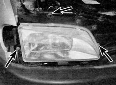
Pic. 7.3. Remove three screws (marked with arrows) and remove headlight
4. Disconnect the electrical connectors for the headlight beam tilt correction motor and the headlamp bulb and remove the headlamp from the vehicle (pic. 7.4).
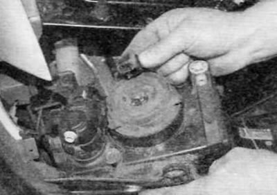
Pic. 7.4. Disconnect the electrical connectors and remove the headlight (early models)
5. If desired, the motor can be removed from the headlight after lifting the tab and turning the motor 90°to release it. After releasing the electric motor, pull the ball joint of the corrector rod from the socket at the rear of the headlight (pic. 7.5, a, b).
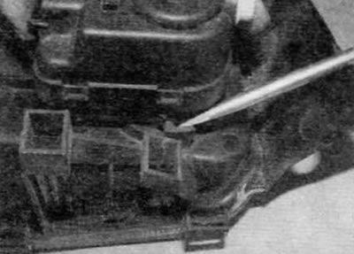
Pic. 7.5, a. To remove the motor, lift the tab and turn the motor 90°...
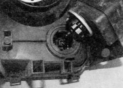
Pic. 7.5b.... then remove the ball joint of the corrector rod from the socket on the headlight (early models)
6. To install the motor, turn the manual height corrector with an Allen key to fully extend the corrector rod. To be able to adjust the home position after installation, calculate the number of turns of the corrector required to fully extend the rod. Insert the ball joint into the socket on the headlight, and then install and secure the electric motor. Return the manual height corrector to the position marked before removal.
7. Connect the electrical connectors and position the headlight in its original position. Install the headlight mounting bolts and tighten them securely.
8. The rest of the installation is performed in the reverse order of removal. Finally, check headlight alignment as soon as possible.
Release models after September 2002
9. Remove the front bumper as described in chapter 11.
10. Turn out the bottom internal and external screws of fastening of a headlight and the top screw (pic. 7.10, a-c).
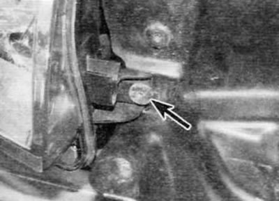
Pic. 7.10, a. Remove the lower inner screw (marked with an arrow)...
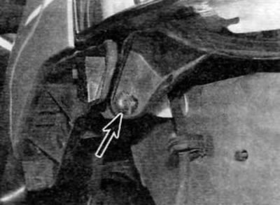
Pic. 7.10, b....lower outer screw (marked with an arrow)...
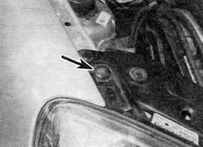
Pic. 7.10, c....and top screw (marked with an arrow) headlight mounts (later models)
11. Using a small screwdriver, slightly lift the upper support arm to disengage the locking tab and remove the headlight (pic. 7.11).
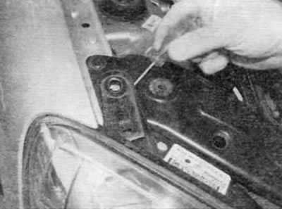
Pic. 7.11. Slightly lift the upper support arm to disengage the locking tab and remove the headlight (later models)
12. Disunite an electric socket and remove a headlight from the car.
13. Installation is carried out in the reverse order of removal. Finally, check headlight alignment as soon as possible.
Front direction indicators
14. The procedure is described as part of the lamp replacement procedure in paragraph 5.
Side turn signal repeaters
15. The procedure is described as part of the lamp replacement procedure in paragraph 5.
Fog lights
16. Fully apply the parking brake. Raise the front of the vehicle and securely jack stands under it (see «Lifting and placing the car on supports»).
17. Turn out screws and for gaining access to a fog lamp partially remove a locker of an arch of a forward wheel.
18. Disunite an electric socket of a fog lamp.
19. Turn out three bolts of fastening, a fog lamp and take a headlight from a forward bumper.
20. Installation is carried out in the reverse order of removal.
Rear lights assy
21. The procedure is described as part of the procedure for replacing the rear light bulb assembly in paragraph 5.
Upper brake light
Models with lifting tailgate
22. The procedure is described as part of the lamp replacement procedure in paragraph 5.
Models with double tailgate
23. Remove the lamp socket as described in the lamp replacement procedure in paragraph 5.
24. Turn out two screws and remove a lantern from a door (pic. 7.24).
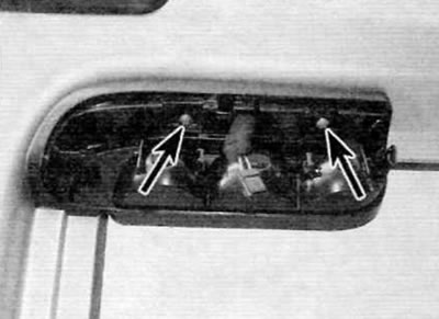
Pic. 7.24. Remove two screws (marked with arrows) and remove the upper brake light (models with double tailgate)
25. Installation is carried out in the reverse order of removal.
License plate lighting
Models with lifting tailgate
26. There is very little room between the license plate light and the plastic outer molding above to remove the light lens. It is highly recommended to first remove the tailgate trim panel (see chapter 11). Then unscrew the three nuts and remove the outer molding (pic. 5.51). The nuts can be accessed through holes on the inside of the tailgate.
27. Through the opening in the tailgate, press the tabs and push the lamp out of the door (pic. 7.27). Disconnect the electrical connector and remove the lamp.
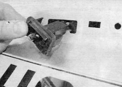
Pic. 7.27. Push in the tabs and push out the license plate light (models with a raised luggage compartment door)
28. Dock the electrical connector and insert the lamp into its original place.
29. Install exterior molding and tailgate trim panel.
Models with double tailgate
30. The procedure is described as part of the lamp replacement procedure in paragraph 5.
