General information
1. On 1.6 liter engines, the valves are actuated by pushers (in which hydraulic compensators are built), located between the camshafts and the upper ends of the valve stems. On 1.4 liter engines, the valves are actuated by valve levers located between the camshaft and the upper end of the valve stem. The valve lever assembly is mounted on the upper plane of the cylinder head with cylinder head bolts. While it is theoretically possible to remove the head mounting bolts and remove the valve arm assembly without removing the head, this is not recommended in practice. After the bolts are removed, the cylinder head gasket will be disturbed, and after installation, the tightness of the gasket will almost certainly be broken. Therefore, removal of the valve arm assembly cannot be done without removing the cylinder head and replacing the cylinder head gasket.
2. On 1.6L engines, the camshafts can be lifted and removed from the cylinder head. On 1.4 liter engines, the camshaft is removed through the right end of the cylinder head, and therefore it cannot be removed without first removing the cylinder head due to lack of space.
Removing
Valve levers (engines 1.4 l)
3. Remove the cylinder head as described in paragraph 11.
4. To disassemble the valve arm assembly, carefully remove the circlip from the right end of the valve arm shaft; hold the valve arm assembly support so that it does not come off the end of the axle under the action of the spring. Remove various elements from the end of the axis, laying out all the elements in the correct sequence (pic. 10.4). Mark the installation position of each item when removing it to ensure proper installation when reassembling. Note. Do not touch the running surfaces of the valve lever roller bearings with your fingers.
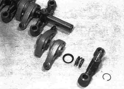
Pic. 10.4. Remove the retaining ring and remove the elements from the axis of the valve levers (engines 1.4 l)
5. To separate the left support from the axle, first unscrew the stud securing the cylinder head cover from the top of the support; this can be done with a stud puller or two nuts that must be tightened against each other (pic. 10.5). After removing the stud, remove the set screw from the hole in the top of the support and remove the valve arm shaft.
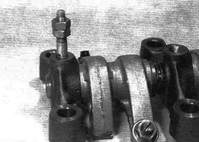
Pic. 10.5. Screw two nuts onto the stud and tighten them relative to each other so that the stud can be unscrewed from the left support (engines 1.4 l)
Camshaft (engines 1.4 l)
6. Remove the cylinder head as described in paragraph 11.
7. Place the head on a workbench, remove the locking tool, and then remove the camshaft sprocket as described in paragraph 7.
8. On early models, remove the ignition coil module from the left end of the cylinder head (see chapter 5B), then remove the bolts and remove the coil support bracket. On later models, remove the bolts and remove the coolant outlet housing from the left end of the cylinder head.
9. Turn away a bolt and remove a persistent fork of a camshaft (pic. 10.9).
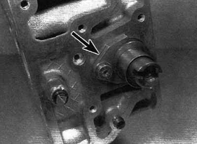
Pic. 10.9. Unscrew the bolt and remove the camshaft thrust fork (marked with an arrow) (engines 1.4 l)
10. Mark installation depth of a cuff of a camshaft concerning a surface of a head of cylinders for ensuring correctness of installation. Using a large flathead screwdriver, carefully pry the seal from the right end of the cylinder head, and then remove the camshaft (pic. 10.10, a, b).
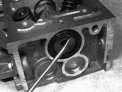
Pic. 10.10, a. Remove cuff...
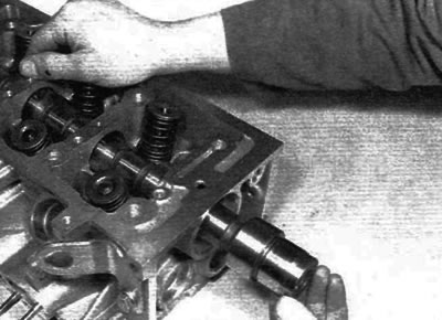
Pic. 10.10, b....then pull the camshaft out of the cylinder head (engines 1.4 l)
Camshafts / tappets (engines 1.6 l)
11. Remove the camshaft sprocket as described in paragraph 7, and then remove the inner timing belt cover as described in paragraph 5.
12. Starting from the outside and working in a cross sequence, gradually and evenly loosen the camshaft bearing housing bolts and remove the housing from the cylinder head (pic. 10.12).
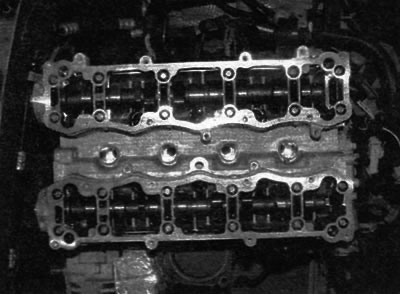
Pic. 10.12. Loosen the camshaft housing bolts evenly and gradually (engines 1.6 l)
13. Identify each camshaft by its position: the intake camshaft is at the rear and the exhaust camshaft is at the front of the cylinder head. Also mark the TDC position of each camshaft to ensure proper installation.
14. Remove camshafts. To remove the corresponding shaft, press on its end from the transmission side to release the opposite end from the corresponding bearing. Remove the camshafts from the cylinder head and remove the cuffs from the ends of the shafts.
15. Prepare 16 small clean plastic containers and number them #1-8 for intake valves and #1-8 for exhaust valves. Alternatively, divide a large container into 16 compartments and number each compartment accordingly. Using a rubber suction cup, remove each pusher in turn and place it in the appropriate compartment. Do not confuse pushrods - this can lead to accelerated wear.
Inspection
Valve lever assembly
16. Inspect the surfaces of the valve lever rollers that are in contact with the camshaft cams for signs of wear and scoring. Replace valve levers that show signs of damage on their rollers. If the rocker roller surface is severely scratched, also inspect the corresponding cam on the camshaft for wear, as both cam surfaces are likely to be worn. Replace worn elements if necessary. The valve arm assembly can be disassembled as described in steps 4 and 5.
17. Inspect the ends of the adjusting screws (setting valve clearances) for signs of wear or damage and replace if necessary.
18. If the valve arm assembly has been disassembled, inspect the valve arm and axle running surfaces for wear and tear. If there are obvious signs of wear, the corresponding valve lever must be replaced (-And) and/or axle.
Camshaft (-s)
19. Examine the working surfaces of the camshaft bearings and cams for signs of wear and scoring. If any of these conditions are present, replace the camshaft. Check the condition of the running surfaces of the bearings on the camshaft journals and in the bearing housing/cylinder head. If the bearing surfaces in the cylinder head show excessive wear, the cylinder head must be replaced.
20. On 1.4L engines, inspect the thrust fork for signs of wear or scoring and replace if necessary.
21. On 1.6 liter engines, inspect the surfaces of the hydraulic tappets that are in contact with the camshaft cams for wear and scoring. Replace pushrod if this condition exists. If the tappet face is badly scratched, also inspect the corresponding cam on the camshaft for wear, as both elements are likely to be worn. If necessary, replace the required elements.
Installation
Valve levers (engines 1.4 l)
22. If the valve arm assembly was disassembled, insert the valve arm shaft into the left mount, aligning the mounting hole in the shaft with the screw hole in the mount. Screw in the set screw and tighten it securely. After tightening the set screw, screw the support pin for the cylinder head cover into the support and tighten it securely. Apply a little clean engine oil to the axle, and then put all the removed parts on the axle, following the correct installation sequence (according to starting position).
Note. Do not touch the running surfaces of the valve lever roller bearings with your fingers. After installing all the elements on the axle, push on the right support and install the retaining ring. Make sure the circlip is properly seated in the corresponding groove on the axle.
23. Install the cylinder head and valve lever assembly as described in paragraph 11.
Camshaft (engines 1.4 l)
24. Clean the bearing surfaces in the cylinder head and on the camshaft, then liberally lubricate the bearings and camshaft lobes. Insert the camshaft into its original position in the cylinder head.
25. Install the thrust fork, fixing the left end of the camshaft. Install the fork mounting bolt and tighten to the specified torque.
26. On early models, install the support bracket and then install the ignition coil module (see chapter 5B). On later models, clean and dry the mating surfaces of the coolant outlet housing and cylinder head, and then apply sealant to the mating surface of the housing. Install the housing to the cylinder head and securely tighten the appropriate bolts.
27. Lubricate the sealing lips of the new seal with clean engine oil, and then install it in place, ensuring the installation depth noted during removal. Use a suitable tubular mandrel, such as a socket, that only rests against the hard outer edge of the cuff. Be careful not to damage the sealing lips during installation. Note that the sealing lips must face inwards.
28. Install the camshaft sprocket as described in paragraph 7.
29. Install the cylinder head as described in paragraph 11.
Camshafts / tappets (engines 1.6 l)
30. Before installation, use a clean rag to remove all traces of oil from the holes for the bolts of the bearing housing in the cylinder head. Also clean (including oil) mating surfaces of the cylinder head and bearing housing.
31. Copiously lubricate the hydraulic tappet holes in the cylinder head and tappets. Carefully insert the tappets into the bores in the cylinder head, ensuring that each tappet is seated in its original hole. Some care will be required to insert the tappets into the holes without being skewed. Be convinced of freedom of turning of each pusher.
32. Copiously lubricate the bearing journals and camshaft cams, and then install the shafts on the cylinder head according to the previously marked position. The alignment groove on the right side of each camshaft must be in position «7 o'clock» on the intake camshaft and in position «8 ocloc'k» on the exhaust camshaft (pic. 10.32).
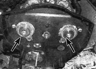
Pic. 10.32. Position the camshafts so that the alignment groove on the intake shaft is in position «7 o'clock», and on the exhaust shaft in position «8 ocloc'k» (marked with arrows) (engines 1.6 l)
33. Apply a bead of silicone based sealant around the perimeter of the mating surfaces and around the bolt holes (pic. 10.33).

Pic. 10.33. Apply silicone sealant to the mating surfaces of the cylinder head (marked with arrows) (engines 1.6 l)
34. Install the bearing housing and gradually, in the prescribed sequence, tighten the bolts to the prescribed torque ( (pic. 10.34).

Pic. 10.34. The sequence of tightening the bolts of the camshaft bearing housing (engines 1.6 l)
35. Install new cuffs (see paragraph 8).
36. Install the timing belt inner cover as described in paragraph 5.
37. Install the camshaft pulleys as described in paragraph 7.
