Note. To properly adjust the timing belt tension on early 1.4L engines, Peugeot/Citroen prescribes the use of a special electronic tool (SEEM C. TRONIC belt tension measuring tool, type 105, and contact plate for valve levers (-J.O132 AE). If this equipment is not available, a rough adjustment can be made using the method described below. If you use the described method, you should check the tension as soon as possible using a special electronic device. Do not travel long distances or use high engine speeds until the belt tension is correct.
General information
1. The timing belt drives the camshaft (-s) and a coolant pump from a toothed pulley at the front end of the crankshaft. If the belt breaks or slips during operation, the pistons can come into contact with the valve heads, resulting in extensive damage resulting in costly repairs.
2. Timing belt should be replaced at prescribed intervals (see chapter 1A) or sooner if it is contaminated with oil or makes noise when running (squeal/creak due to uneven wear).
3. If the timing belt is removed, it is recommended to check the condition of the coolant pump at the same time (check for signs of coolant leakage). This will help avoid the need to remove the belt at a later stage if the coolant pump fails.
4. On late 1.4L engines, an automatic timing belt tensioner is used to maintain proper timing belt tension after the initial adjustment procedure. The auto tensioner can be identified by the indicator lever and tension position marks on the side of the tensioner housing (pic. 6.33). If this type of tensioner is installed, follow the procedures for later 1.4L engines when installing the timing belt.
Removing
5. Disconnect the ground wire from the battery (see «Disconnecting the battery»).
6. Align the mounting holes for the engine/camshaft assembly as described in paragraph 3, and lock the camshaft sprocket and flywheel.
Warning. Do not attempt to crank the engine with the locking tools installed.
7. Remove the remaining timing belt covers as described in paragraph 5.
Engines 1.4 l
8. Loosen the timing belt tensioner pulley nut (pic. 6.8). Turn the pulley approximately 60°clockwise with a wrench inserted into the hole in the pulley hub, and then re-tighten the nut. Early engines will require an 8mm square wrench, and later auto-tensioner engines will require an internal hex wrench.
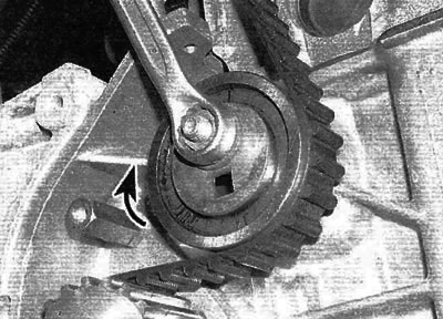
Pic. 6.8. Loosen the nut and turn the idler pulley clockwise to release tension from the timing belt (engines 1.4 l)
Advice. If you're having trouble getting a square tool to fit into the idler pulley, buy an 8mm square rod for a standard doorknob at the hardware store and shorten it to the correct length (A). Insert a rod into the pulley hub and rotate the pulley with an 8mm wrench (IN).
9. If the timing belt is to be used further, mark the direction of rotation on the belt with white paint or a marker (if the marking is not visible). Remove the belt from the toothed pulleys.
Engines 1.6 l
10. Loosen the nut securing the timing belt tensioner pulley and, using a hex wrench, turn the pulley clockwise until the indicator lever is in the minimum tension position (pic. 6.10). Temporarily tighten the idler pulley nut in this position.
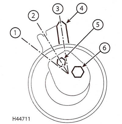
Pic. 6.10. Timing belt tensioner (engines 1.6 l)
1. Minimum tension position; 2. Normal tension position; 3. Maximum tension position; 4. Indicator lever; 5. Hex key hole; 6. Idler pulley bolt
11. If the timing belt is to be used further, mark the direction of rotation on the belt with white paint or a marker (if the marking is not visible). Remove the belt from the toothed pulleys.
All engines
12. Carefully check the timing belt for signs of uneven wear, delamination or oil contamination. Pay special attention to tooth cavities. Replace the belt if there is even the slightest doubt about its condition. If the engine is being overhauled and the vehicle has more than 60,000 km with a particular belt, it is mandatory to replace the belt, regardless of its external condition. The cost of a new belt is not comparable to the cost of repairing an engine in the event of a broken belt. If signs of oil contamination are found, locate the leak and repair the cause of the leak. Wash the engine in the area of the timing belt, as well as all relevant elements until all traces of oil are completely removed.
13. Before installation, thoroughly clean the toothed pulleys of the timing belt. Check that the tensioner and pulleys rotate freely without binding. If necessary, replace the pulleys as described in paragraph 7. Make sure the locking tools are still inserted as described in paragraph 3.
Installation
(early 1.4L engines)
14. Move the timing belt to its original position, making sure that the arrows on the belt point in the direction of belt rotation (clockwise when viewed from the right end of the engine).
15. Do not sharply twist the timing belt when installing it. Put the belt on the crankshaft and camshaft pulleys. Make sure that the front section of the belt is tensioned, that is, that all the slack falls on the section of the belt where the idler pulley is located. Slide the belt over the water pump sprocket and idler pulley. Make sure that the teeth of the belt are centered on the teeth of the toothed pulleys.
16. Loosen the idler pulley nut. Turn the pulley counter-clockwise to completely remove any slack in the timing belt, and then re-tighten the nut (pic. 6.16). Tension the timing belt as described under the appropriate subheading.
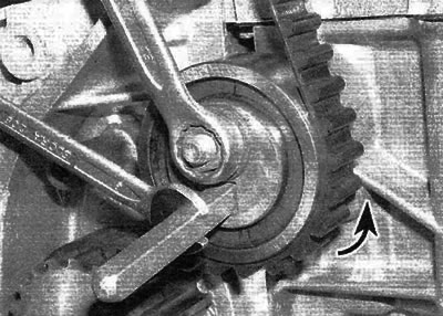
Pic. 6.16. Turn the idler pulley counterclockwise to fully take up the slack in the timing belt, and then tighten the pulley nut
Tensioning without a special electronic measuring device
Note. If you use the described method, you should check the tension as soon as possible using a special electronic device.
17. If a special tool is not available, coarse adjustment can be made as described below. Loosen the nut securing the idler pulley and turn the pulley counterclockwise so that the belt can be twisted 90°in the middle of the area between the crankshaft and camshaft toothed pulleys. The belt deflection in the middle of the section between these pulleys should be approximately 6.0 mm. Hold the idler pulley in this position and tighten the nut.
18. Remove the locking tools from the camshaft sprocket and flywheel.
19. Using a suitable socket and extension, turn the crankshaft at the crankshaft sprocket bolt four full turns clockwise (viewed from the right side of the engine).
Warning. Never turn the crankshaft counterclockwise.
20. Loosen the idler nut, tighten the belt as described in step 17 and tighten the idler nut to the specified torque.
21. Rotate the crankshaft two more turns clockwise and check that the alignment holes in the camshaft sprocket and flywheel are still properly aligned.
22. If so, install the timing belt covers as described in paragraph 5 and connect the ground wire to the battery.
Tensioning using a special electronic measuring device
23. Install the belt tensioner on the front section of the timing belt, approximately midway between the crankshaft and camshaft sprocket. Position the idler pulley so that the belt is tensioned enough to show 44 SEEM units, and then re-tighten the nut.
24. Remove the locking tools from the camshaft sprocket and flywheel and remove the gauge from the belt.
25. Using a suitable socket and extension, turn the crankshaft at the crankshaft sprocket bolt four full turns clockwise (viewed from the right side of the engine). Never turn the crankshaft counterclockwise. Install a locking tool on the flywheel and check that the locating hole in the camshaft sprocket is properly aligned.
26. To ensure the accuracy of the readings, it is necessary to remove the load created by the valve springs from the camshaft, for which it is necessary to install a contact plate for the valve levers (—).0132 AE. Remove the cylinder head cover (see paragraph 4), and then loosen the eight valve arm contact bolts on the valve arm contact plate. Install the contact plate on the studs of the cylinder head cover, observing the correct installation direction, and secure it with nuts from the cover (pic. 6.26). Tighten the contact bolt of each valve lever just enough to move the valve levers away from the camshaft lobes. Do not overtighten the contact bolts, otherwise the valves will come into contact with the pistons.
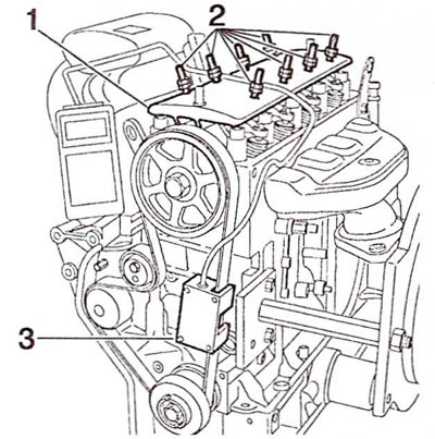
Pic. 6.26. Install the valve lever plate (1) on the cylinder head and using contact bolts (2), lift the valve arms away from the camshaft. Pay attention to the correct position of the measuring tool (3)
27. Install the measuring tool on the belt, loosen the idler pulley mounting nut and gradually loosen the idler pulley until the gauge reads in the range of 29-33 SEEM units. Tighten the idler pulley nut to the specified torque.
28. Remove the gauge from the belt, then unscrew the nuts and remove the valve lever contact plate from the cylinder head.
29. Remove the flywheel locking tool and then rotate the crankshaft an additional four full turns clockwise. Install the flywheel locking tool and make sure the camshaft alignment hole is correctly aligned with the hole in the cylinder head.
30. If so, install the timing belt covers and cylinder head cover as described in paragraphs 4 and 5. Note. If the valve lever adjusting screws have been moved, adjust the valve clearances before installing the cylinder head cover.
Installation
(late engines 1.4 l)
31. Bring the timing belt to its normal position, making sure that the arrows on the belt are facing in the direction of rotation of the belt (clockwise when viewed from the right end of the engine).
32. Do not sharply twist the timing belt when installing it. Put the belt on the crankshaft and camshaft pulleys. Make sure that the front section of the belt is tensioned, that is, that all the slack falls on the section of the belt where the idler pulley is located. Slide the belt over the water pump sprocket and idler pulley. Make sure the belt teeth are centered.
33. Remove the crankshaft and camshaft locking tools, and then loosen the idler pulley mounting nut and, using a hex wrench, turn the pulley counterclockwise until the indicator lever is in the maximum tension position (pic. 6.33). Tighten the pulley nut.
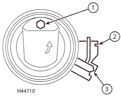
Pic. 6.33. Timing belt tensioner (late engines 1.4 l) 1. Hex key hole; 2. Normal tension position; 3. Maximum tension position
34. Using a suitable socket, rotate the crankshaft at the crankshaft pulley bolt 10 full turns and install the crankshaft locking tool as described in paragraph 3.
35. Make sure the valve timing is correct, insert the tool to lock the camshaft pulley (paragraph 3). If the tool cannot be inserted, release the tensioner, remove the belt, install the locking tools and repeat the steps from step 31 again.
36. Remove the crankshaft and camshaft locking tools.
37. Hold the hex wrench in the idler pulley to maintain tension, then loosen the pulley mounting nut and turn the tensioner to bring the indicator arm to the normal tension position (pic. 6.33). Tighten the pulley nut to the specified torque.
38. Rotate the crankshaft two full turns and check that the crankshaft and camshaft locking tools can still be inserted.
39. The rest of the installation is performed in the reverse order of removal.
Installation
(engines 1.6 l)
40. Bring the timing belt to its original position, making sure that the arrows on the belt are facing in the direction of rotation of the belt (clockwise when viewed from the right end of the engine). Keep in mind that the new belt has three marks that match the marks on the crankshaft and camshaft sprocket (pic. 6.40).
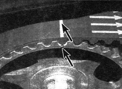
Pic. 6.40. Pay attention to the marks on the timing belt that match the marks on the camshaft and crankshaft sprocket (engines 1.6 l)
41. Do not sharply twist the timing belt when installing it. Slide the belt over the crankshaft and camshaft sprocket aligning the marks on the belt with the marks on the crankshaft and camshaft sprocket. Make sure that the front section of the belt is tensioned, that is, that all the slack falls on the section of the belt where the idler pulley is located. Slide the belt over the water pump sprocket, idler pulley and idler pulley. Make sure that the teeth of the belt are centered on the teeth of the toothed pulleys.
42. Insert a hex wrench into the tension pulley, loosen the pulley mounting nut and turn the wrench to bring the indicator arm to the maximum tension position (pic. 6.10). Tighten the tensioner pulley nut securely.
43. Remove the camshaft and crankshaft locking tools, rotate the crankshaft four full turns clockwise and reinstall the crankshaft locking tool.
44. Insert a hex wrench into the tensioner, unscrew the nut and turn the tensioner with a wrench until the indicator lever is in the normal tension position (pic. 6.10). Tighten the tensioner nut to the specified torque.
45. Remove the crankshaft locking tool and turn the crankshaft two full turns clockwise. Check the position of the tensioner indicator arm; it should not be further than 2.0 mm from the normal tension position. If not, repeat the belt installation procedure from step 40.
46. Install the timing belt covers as described in paragraph 5, and then finally connect the battery.
