Engine ventilation system
1. The elements of this system do not require any other attention than regular checking of the cleanliness and performance of the hoses.
Evaporative Emission System
Examination
2. If you suspect a system problem, disconnect the hoses from the canister and purge control valve and check for cleanliness by blowing them out. If valve failure is suspected (-ov) purge control or carbon filter, they should be replaced.
Adsorber replacement
3. The adsorber is located behind the right forward wing. To gain access to the adsorber, fully apply the parking brake, raise the front of the vehicle and place it on secure supports (see «Lifting and placing the car on supports»). Remove the wheel, then remove the screws from the base of the wheel arch locker. Remove the clips and remove the locker from under the wing.
4. On early models, unscrew the bolt, release the canister from the corresponding clip and remove it from under the wing (pic. 2.4). On later models, release the canister from the appropriate clips and remove it from under the wing. On all models, mark the hoses to ensure correct installation.
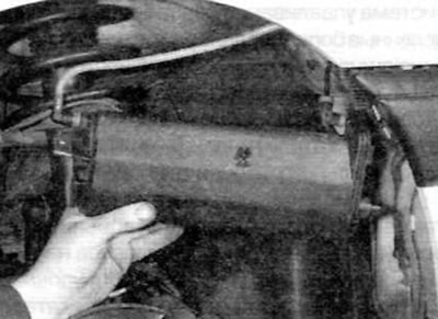
Pic. 2.4. Remove the canister from under the right fender
5. Release collars, then disconnect both hoses and remove an adsorber from the car. If crimp type clamps are used, cut them and discard. When installing, use standard worm gear clamps (screw) clamp. If the hoses are equipped with quick couplings, press the center bushing with a small flathead screwdriver and then disconnect the hose from the canister (pic. 2.5). On later models, also disconnect the purge valve electrical connector.
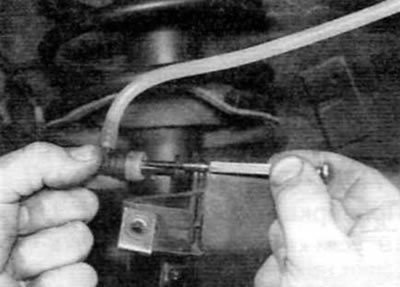
Pic. 2.5. To disengage the hose quick coupler, press the center bushing with a small flathead screwdriver
6. Installation is carried out in the reverse order of removal. Connect hoses properly.
Valve replacement (-ov) purge
7. On early models, the purge valve is located on the right side of the engine compartment (pic. 2.7). On later models, the purge valve is integrated with the canister and cannot be replaced separately. 8 To replace the purge valve on early models, first disconnect the wire «masses» from battery (see «Disconnecting the battery»).
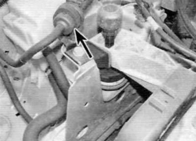
Pic. 2.7. On early models, the purge valve (marked with an arrow) located on the right side of the engine compartment
9. Press the clip and disconnect the valve electrical connector. Disconnect the hoses from both ends of the valve, then release the valve from the appropriate clamp or clamp and remove it from the engine compartment, noting for yourself how it is installed.
10. Installation is carried out in the reverse order of removal. Connect the valve properly and connect the hoses securely.
Emission control system
Examination
11. The effectiveness of a catalytic converter can only be verified by measuring the composition of the exhaust gases with a good quality, accurately calibrated gas analyzer. If this equipment is present, it must be connected and installed in accordance with the manufacturer's instructions.
12. If the level of CO at the tailpipe is too high, the vehicle should be checked by a Peugeot/Citroen dealer or other specialist who has special diagnostic equipment and can fully check the engine management system. If their check shows no malfunction, then the malfunction lies in the catalytic converter, which should be replaced as described in chapter 4A.
Replacing the catalytic converter
13. Refer to chapter 4A.
Oxygen sensor replacement (-ov)
Note. The oxygen sensor is very «delicate» device. It will not work if it has been dropped or hit, if the power supply has been interrupted, or if it has been cleaned with cleaning agents.
Note. Later engines meeting the L4 emission standard are equipped with a rear oxygen sensor located after the catalytic converter. The removal and installation procedures are the same for both sensors.
14. Trace the wiring from the oxygen sensor (which is screwed into the upper part of the downpipe of the exhaust system or into the exhaust manifold) to the top of the gearbox. Disconnect both electrical connectors and release the electrical wiring from the appropriate clips or clamps (pic. 2.14).
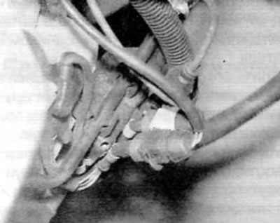
Pic. 2.14. On early models, the oxygen sensor electrical connectors are fixed to the front of the transmission
15. Turn out the gauge from a reception pipe of system of release or a collector and remove it together with a sealing washer.
16. Installation is carried out in the reverse order of removal, using a new sealing washer. Apply a small amount of high temperature grease to the sensor threads before installing the sensor. Tighten the sensor securely and route the wiring properly to avoid contact with the exhaust system or engine.
Secondary air injection
Examination
17. If the air injection pump does not appear to be working properly, the vehicle should be taken to a Peugeot/Citroen dealer or an engine diagnostic technician who can thoroughly check the entire engine management system, including the pump, using dedicated diagnostic equipment (see chapter 4A).
18. The air injection valve can only be checked after it has been removed. The valve should only allow air to flow in one direction when blowing through the fitting on the pump side. If it is not, it is defective and should be replaced.
Air pump replacement
19. The air pump is located on the left side of the engine compartment.
20. To gain access to the pump, remove the air filter housing as described in chapter 4A.
21. Turn out bolts, and then disconnect vacuum hoses and disconnect an electric socket and remove the pump from the car.
22. Installation is carried out in the reverse order of removal.
Air injection valve replacement
23. The air injection valve is mounted on the front of the cylinder head.
24. Disconnect the air hose from the valve.
25. Turn out bolts of fastening of an adapter of the valve to top of an exhaust manifold (pic. 2.25).
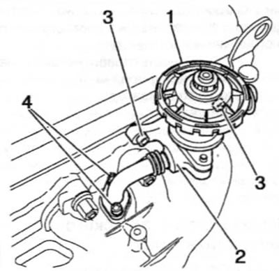
Pic. 2.25. Secondary air injection valve (later models with 1.4 l engine)
1. Air injection valve
2. Valve adapter
3. Bolts of fastening of the valve to a head of cylinders
4. Bolts for fastening the adapter to the manifold
26. Turn out bolts of fastening of the valve to a forward part of a head of cylinders, and then remove the valve in gathering with an adapter from the engine.
27. If necessary, remove the nuts and separate the valve and adapter from each other. Remove the gasket and discard it; when installing, use a new one.
28. Installation is carried out in the reverse order of removal. Use a new gasket (if necessary) and tighten the nuts/bolts to the specified torque.
