Note. The shift lever mechanism is not adjustable. If shifting is difficult or there is excessive play in the shift lever, disassemble the linkage and check the condition of the ball joints and bushings of the link axles as described below.
Removing
1. Fully apply the parking brake. Raise the front of the vehicle and securely jack stands under it (see «Lifting and placing the car on supports»). Remove engine protection (if applicable).
2. Remove the battery, battery shelf, and base plate as described in chapter 5A. Depending on the model and working space, to facilitate access to the wiring on top of the transmission, remove the air filter and the remaining elements of the intake air line, as described in the appropriate part chapter 4.
Gearbox MA5 (release models up to 1998)
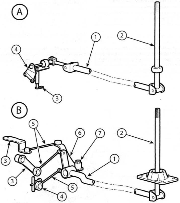
3. Loosen the nut (with puck), then remove the axle at each end of the selector rod (pic. 3.3). Disconnect the linkage from the gearshift lever in the passenger compartment and from the gearshift lever on the gearbox and remove it from under the car. Remove the spacers and axle bushings from the shift lever in the passenger compartment and the shift lever on the gearbox.

Pic. 3.3. The location of the lever gear shift mechanism on the MA5 gearbox
A. Models up to 1998
B. Models since 1998
1. Gear selection link
2. Gear lever
3. Gear selector on gearbox
4. Fixed support bracket
5. Pulls
6. Bellcrank
7. Crank axle
4. Remove the two nuts securing the shift lever support bracket to the transaxle case, and then remove the bracket and shift lever assembly from the transaxle.
5. Inspect all linkage components for signs of wear or damage, paying particular attention to axle bushings, and replace worn components as necessary.
6. To remove the shift lever, remove the center console as described in chapter 11, then remove the four nuts and remove the shift lever from under the vehicle.
7. Remove the lower boot from the base of the gear lever, and then unhook the lever base plate. To gain access to the ball joint of the gear lever, slide the top boot up the lever. Inspect the lever elements for signs of wear or damage, paying special attention to the rubber boots, and replace the elements if necessary. After releasing the fastening ring, the lever can be separated from the corresponding base plate.
Gearbox MA5 (release models since 1998)
8. Turn away a nut and remove an axis of fastening of draft of a choice of transfers to the basis of the gear lever (pic. 3.3). Remove the axle bushings from the shift lever.
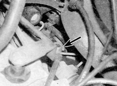
9. Using a flathead screwdriver, carefully separate the ball joints of the two selector rods from the lever on the gearbox and the fixed bracket on the gearbox (pic. 3.9). Unhook the gear selector link from the crankshaft ball joint and remove it, together with the two links, from under the vehicle.

Pic. 3.9. Carefully remove the linkages from their respective ball joints on the gearbox
10. Remove the protective cap, then loosen and remove the crankshaft axle bolt and washer. Carefully separate the crank link ball joint from the link on the transmission and remove the crank link and link.
11. Inspect all linkage components for signs of wear or damage, paying special attention to axle bushings and linkage ball joints, and replace worn components as necessary. If necessary, the gear lever can be removed and disassembled, as described in p.p. 6 and 7.
Gearboxes VEZ/5 and BE4/5
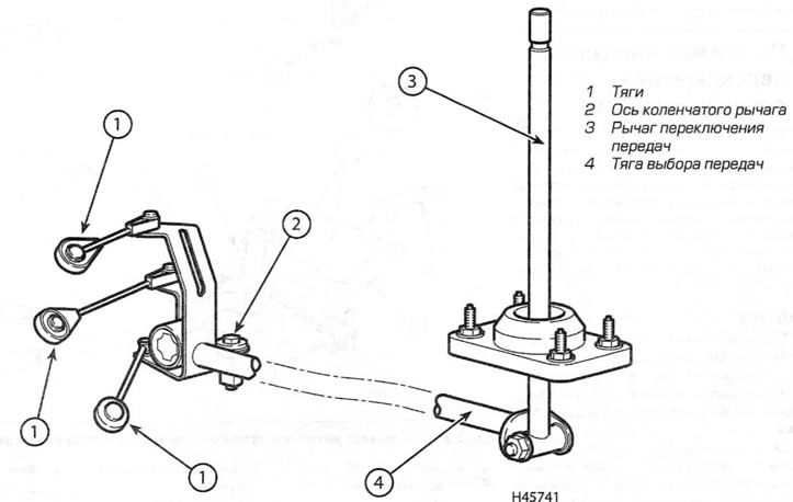
12. Turn away a nut and remove an axis of fastening of draft of a choice of transfers to the basis of the gear lever (pic. 3.12).

Pic. 3.12. The location of the lever mechanism for gear shifting on gearboxes VEZ / 5 and BE4 / 5
Remove washers and/or bushing (-And) from the gear lever.
13. Using a flathead screwdriver, carefully separate the ball joints of the three selector rods from the two levers on the transmission and the fixed bracket. Unhook the selector link from the crankshaft ball joint and remove it, along with the three links, from under the vehicle.
14. If applicable, carefully remove the plastic cover from the linkage crankshaft to subframe mounting pin.
15. Loosen and remove the crankshaft and washer or nut and washer from the crankshaft, and then move the crankshaft and remaining linkage out from under the vehicle. If applicable, remove the spacer and bushings from the center of the crank arm.
16. Inspect all elements of the linkage for signs of wear or damage, paying special attention to the bushings and ball joints of the rods, and replace worn elements if necessary. If necessary, the gear lever can be removed and disassembled, as described above in p.p. 6 and 7.
Installation.
17. Installation is carried out in the reverse order of removal, taking into account the following points:
- A) Apply some multipurpose grease to the crankshaft ball joint. Do not lubricate linkage ball joints or axle bushings.
- b) Securely fix all rods on their respective ball joints.
- V) If applicable, install air cleaner elements (see chapter 4A, 4B or 4B), base plate, battery shelf and batteries, chapter 5A) and center console (see chapter 11).
