Examination
1. The reversing light circuit is controlled by a plunger-type switch screwed into the top of the transmission case. If a fault occurs in the electrical circuit, first check for a blown fuse.
2. To gain access to the switch, remove the battery, battery tray, and base plate as described in chapter 5A. Depending on the model and working space, to facilitate access to the wiring on top of the transmission, remove the air filter and the remaining elements of the intake air line, as described in the appropriate part chapter 4.
3. To test the switch, disconnect the electrical connector. Using a multimeter (configured for resistance testing) or self-powered test pump, make sure that the electrical circuit between the switch terminals is closed only when reverse gear is engaged. If this is not the case and there are no obvious breaks or other damage to the wiring, then the switch is defective and must be replaced.
Removing
4. To gain access to the switch, remove the battery, battery tray, and base plate as described in chapter 5A. Depending on the model and working space, to facilitate access to the wiring on top of the transmission, remove the air filter and the remaining elements of the intake air line, as described in the appropriate part chapter 4.
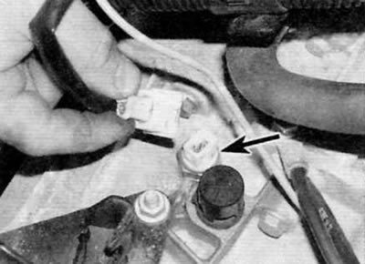
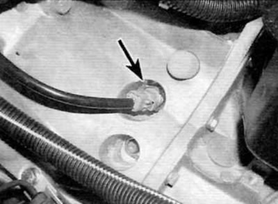
5. Disconnect the electrical connector, then unscrew the switch from the gearbox housing and remove it together with the sealing washer (pic. 5.5, a, b).

Pic. 5.5, a. Location of the reversing light switch (marked with an arrow) on the MA5 gearbox...

Pic. 5.5b....and on the BE4/5 gearbox
Installation
6. Install a new sealing washer on the switch, then screw it into the appropriate hole in the top of the gearbox housing and tighten it to the specified torque. Connect the electrical connector and check the operation of the electrical circuit. Install the items removed to gain access.
