Note. Do not put the car on wheels when one or both half shafts are removed, as this may damage the bearing (-ov) wheels (wheels). If vehicle movement is unavoidable, temporarily insert the outer end of the axle shaft (-to her) into the hub (-s) and tighten the nut (-And) hubs: in this case under the inner end (-tsy) axle shafts (-to her) a support should be installed or suspended. e.g. with a suitable cable to the underside of the vehicle. Do not allow the axle shaft to hang freely under its own weight. When installing, use a new axle shaft nut, lower arm ball joint clamp bolt nut, and anti-roll bar nut
Removing
1. Fully apply the parking brake. Raise the front of the vehicle and securely jack stands under it (see «Lifting and placing the car on supports»).
2. Remove the corresponding front wheel.
3. Drain the gear oil as described in chapter 7.
4. Remove the R-clamp and remove the retaining cap from the axle shaft nut (pic. 2.4, a, b).
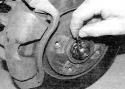
Pic. 2.4, a. Remove the R-clip...
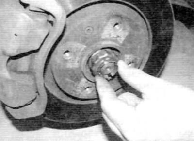
Pic. 2.4, b.... and remove the retaining cap from the axle shaft nut
5. To prevent the wheel hub from turning when the axle shaft nut is released, make a holding tool and use the two wheel bolts to secure the tool to the wheel hub.
Advice. The tool for holding the front hub when releasing the axle shaft nut can be made from two pieces of steel strip (long and short) and three pairs of nuts and bolts; one nut with a bolt forms the axis of the fork tool.
6. After securing the holding tool, use the socket and extension to unscrew the nut securing the axle shaft (pic. 2.6). If necessary, place a suitable support under the socket to prevent the socket from slipping off the nut. This nut is very tight; make sure that there is no risk of the car jumping off the supports when the nut is loosened.

Pic. 2.6. After installing the holding tool, use the socket and extension to unscrew the axle shaft nut
7. Turn away a nut and remove a washer of fastening of a rack to the anti-roll bar. Rotate the stand to the side.
8. Turn away a nut, then take a tightening bolt of a spherical joint of the lower suspension bracket from a rotary fist. Throw away the nut; when installing, use a new (pic. 2.8).
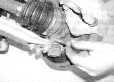
Pic. 2.8. Loosen the nut and remove the lower ball joint clamp bolt from the steering knuckle
9. Drive a small chisel into the slot on the steering knuckle to widen the slot slightly to remove the ball joint pin (pic. 2.9, a). Pull the lower control arm down to release the ball joint pin from the steering knuckle. To do this, you will need to use a long rod and a wooden block, which is brought under the front subframe. Lock the rod to the suspension arm as shown. It is preferable to use a chain, or, alternatively, a strong collar or cable. Press the outer edge of the rod down to release the ball joint from the steering knuckle (pic. 2.9, b).
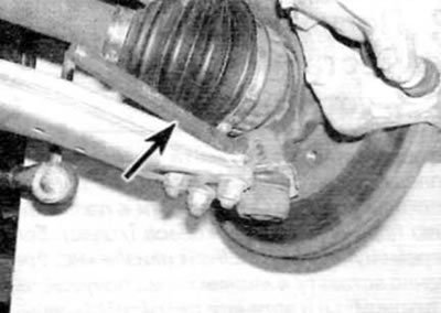
Pic. 2.9, a. With a small chisel (marked with an arrow) open the slot in the steering knuckle...
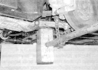
Pic. 2.9, b....then, using a chain pin or similar device, pull the lower control arm down; use a stretcher as a fulcrum
10. After releasing the ball joint, remove the protective plate that is installed on the ball joint pin (pic. 2.10).
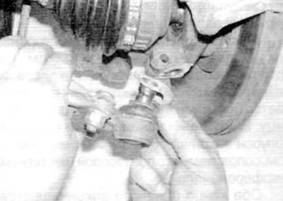
Pic. 2.10. When releasing the ball joint, remove the protective plate from the ball joint pin
Left axle
11. Gently pull the steering knuckle out and remove the outer axle joint from the hub (pic. 2.11). If necessary, the axle shaft can be knocked out of the hub using a soft-faced hammer. When retracting the steering knuckle, be careful not to deform the brake hose or, if applicable, the ABS wheel speed sensor wiring.
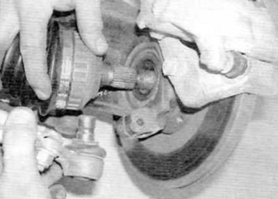
Pic. 2.11. Pull the steering knuckle out and remove the outer axle joint from the hub
12. Support the axle shaft, and then remove the inner joint from the gearbox, making sure not to damage the cuff of the axle shaft (pic. 2.12). Remove the half shaft from the vehicle.
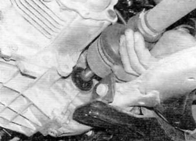
Pic. 2.12. Support the axle shaft, and then remove the inner joint from the gearbox
Right half shaft
13. Loosen the nuts on the two intermediate bearing mounting bolts, and then rotate the bolts 90°so that their offset heads are located away from the bearing outer race (pic. 2.13).
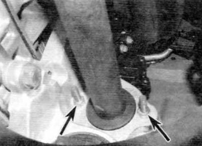
Pic. 2.13. On the right half shaft, loosen the nuts on the bolts of the intermediate support (marked with arrows), and then turn the bolts 90°
14. Gently pull the steering knuckle out and remove the outer axle joint from the hub. If necessary, the axle shaft can be knocked out of the hub using a soft-faced hammer. When retracting the steering knuckle, be careful not to deform the brake hose or, if applicable, the ABS wheel speed sensor wiring.
15. Support the outer end of the axle shaft and then pull on the inner axle shaft to release it from the gearbox and the intermediate bearing from the appropriate support bracket (pic. 2.15). Remove the half shaft from the vehicle.
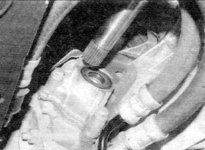
Pic. 2.15. Release the inner end of the axle shaft from the gearbox and the intermediate bearing from the corresponding support bracket
Installation
16. Before installing the axle shaft, inspect the axle shaft seal in the gearbox for signs of damage or deterioration and, if necessary, replace it as described in chapter 7. (Given the difficulty of access, it is recommended to replace the cuff without fail.)
17. Thoroughly clean the splines of the axle shaft and the holes in the gearbox and hub. Apply a thin layer of grease to the sealing lips of the cuff, as well as to the splines and shoulders of the axle shaft. Make sure that the clamps on all covers are secure.
Left axle
18. Move the axle shaft to the installation site and engage the splines of the hinge with the splines of the differential side gear, being extra careful not to damage the cuff. Fully insert the hinge into place.
19. Insert the splines of the outer hinge into the splined hole of the hub and insert the hinge all the way into the hub.
20. Install the skid plate on the lower arm ball joint, and then, using the same method as for removal, insert the ball joint pin into the steering knuckle, making sure that the protrusion on the skid plate correctly fits into the clamping slot. Insert the ball joint clamp bolt, and then screw on the new nut and tighten it to the specified torque.
21. Lubricate the inner surface and threads of the new axle shaft nut with clean engine oil and screw it onto the end of the axle shaft. Using the method used for removal, hold the hub from turning and tighten the axle shaft nut to the specified torque. Make sure the hub can rotate freely.
22. Fix the lock cap on the axle shaft nut so that one of its cutouts fits into the hole in the axle shaft. Secure the cap with the R-clip.
23. Install the rack on the anti-roll bar, install the washer and screw a new nut. Tighten the nut to the specified torque.
24. If necessary, dock the ABS wheel sensor electrical connector. At the same time, lay the wiring correctly and secure it with all necessary clamps and clamps.
25. Fill the gearbox with the prescribed gear oil in the specified quantity as described in chapter 7.
26. Finally, install the wheel, lower the vehicle and tighten the wheel bolts to the prescribed torque.
Right half shaft
27. Verify that the intermediate bearing rotates smoothly without binding or excessive play between the inner and outer races. If necessary, replace the bearing as described in paragraph 5.
28. Apply some grease to the outer race of the intermediate bearing and then thread the inner end of the axle shaft through the bearing support bracket.
29. Gently insert the inner splined end of the axle shaft into the splined hole in the differential side gear. Be careful not to damage the cuff. Align the intermediate bearing with the appropriate support bracket and fully insert the axle shaft into place. If necessary, use a soft-faced hammer to drive the bearing outer race into the mounting hole in the support bracket.
30. Enter the splined end of the external CV joint into the splined hole in the hub and bring the joint to its original position in the hub.
31. Make sure the intermediate bearing is correctly aligned, then turn the intermediate bearing bolts back 90°so that their offset heads are against the bearing outer race. Tighten nuts to specified torque.
32. Follow the steps described above in p.p. 20-26.
