External hinge
1. Remove the axle shaft as described in paragraph 2.
2. Remove the inner constant velocity joint and cover, as described in p.p. 13-18. It is recommended to replace the inner cover regardless of its external condition.
3. Release the two collars of the outer boot, and then slide the boot from the inner end of the axle shaft.
4. Remove as much as possible «old» lubricants (do not use solvent) with a hinge so that you can inspect its elements.
5. Check the axle shaft spider and outer member yoke for signs of wear, pitting, or other defects on the running surfaces. Also check that the outer element rotates smoothly and easily with no signs of binding.
6. If the spider or outer member shows signs of wear or damage upon inspection, the entire axle shaft will need to be replaced as a unit, as no members are supplied separately. If the hinge components are in satisfactory condition, obtain a repair kit from your Peugeot/Citroen dealer, consisting of a new boot, clamps and correct grade of grease in the correct quantity (pic. 3.6).
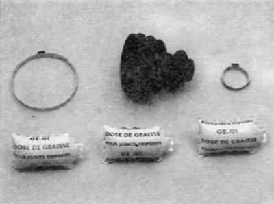
Pic. 3.6. Elements of the repair kit for the cover of the external hinge of the axle shaft
7. Wrap the splines on the inner end of the axle shaft, and then carefully slide the outer boot onto the axle shaft (pic. 3.7).
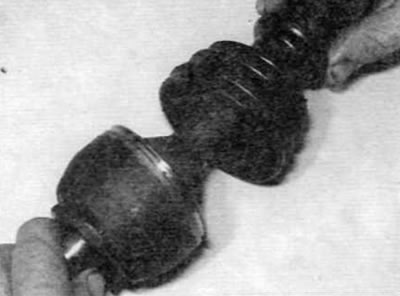
Pic. 3.7. Slide the outer joint cover onto the axle shaft
8. Pack the joint with grease from the repair kit (pic. 3.8). Inject grease into the bearing races while turning the pivot. Stuff the rubber boot with the remaining grease.
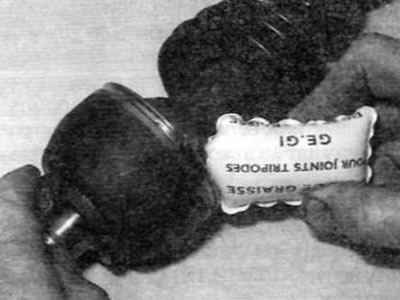
Pic. 3.8. Pack the joint with grease from the repair kit
9. Put the cover on the hinge and make sure that the edges of the cover fit correctly into the grooves on the axle shaft and hinge. Pry up the outer edge of the case to equalize the air pressure under the case.
10. Install a large metal tie on the case. Remove any slack in the boot strap by gently squeezing the protruding section of the strap. In the absence of a special tool, use side cutters. Fix the small collar using the same procedure (pic. 3.10). Ensure that the CV joint moves freely in all directions before proceeding to the next step.
11. Install the inner constant velocity joint as described in p.p. 21-28.
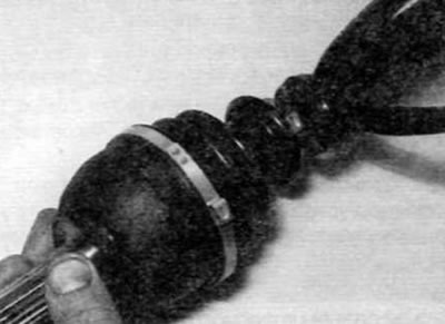
Pic. 3.10. Fixing the cover clamp with side cutters
Internal hinge
12. Remove the axle shaft as described in paragraph 2.
13. Clamp the axle shaft in a vice with soft jaws, and then, using pliers, carefully bend the protrusion on the periphery of the cover of the outer element of the constant velocity joint (pic. 3.13).
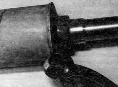
Pic. 3.13. Bending the edge of the cover of the outer hinge element
14. After the protrusion on the cover is completely released, pull the outer hinge element off the cover and remove the spring and thrust cap from the end of the axle shaft. Remove the o-ring from the outside of the outer element and discard it.
15. Fold the cover back and wipe off excess grease from the hinge tripod. If the rollers are not secured to the hinge with retaining rings, wrap the hinge with adhesive tape to hold the rollers.
16. Using paint or a hammer with a center punch, mark the position of the tripoid relative to the axle shaft. Using circlip pliers, remove the circlip securing the pivot to the axle shaft (pic. 3.16).
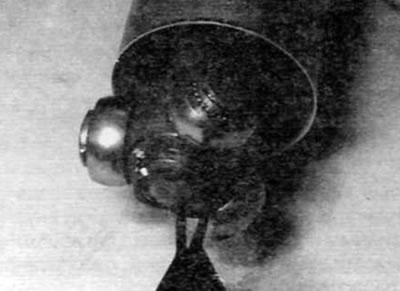
Pic. 3.16. Removal of a lock ring of a tripod of an internal hinge
17. Now you can remove the tripoid. If it is tight, remove it from the end of the axle shaft with a 2- or 3-jaw bearing puller. Fix the grips of the puller behind the inner hinge element so. so that they do not come into contact with the rollers (pic. 3.17, a, b). Alternatively, support the inner member of the 3-finger joint and press the axle shaft out of the joint using a hydraulic press. Make sure that the load is not applied to the rollers of the hinge.
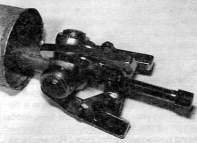
Pic. 3.17 a. Using a 3-jaw puller, remove the inner hinge tripod
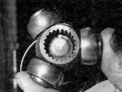
Pic. 3.17b. Removing the inner hinge tripod. Pay attention to installation marks
18. After removing the tripoid, remove the cover and the inner retaining ring from the end of the axle shaft.
19. Erase as much as possible «old» lubricants (do not use solvent) with a hinge so that you can inspect its elements. Be extremely careful not to remove alignment marks made before removal, especially if they were made with paint.
20. Inspect the tripod, rollers, and outer member for signs of damage or wear. Check the smoothness of the movement of the rollers on the fingers of the tripod. In the presence of wear, the axle shaft assembly must be replaced; no hinge elements are supplied separately. If the hinge components are in good condition, obtain a repair kit from your Peugeot/Citroen dealer that consists of a new rubber boot assembly with outer cover, retaining ring, thrust cap, spring, O-ring and the correct amount of grease (pic. 3.20).
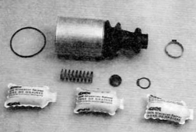
Pic. 3.20. Elements of the repair kit for the inner joint of the axle shaft
21. Tape the splines on the end of the axle shaft and carefully slide the inner circlip and cover assembly onto the axle shaft (pic. 3.21, a, b).
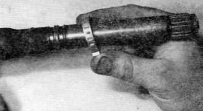
Pic. 3.21 a. Slide on the inner circlip...
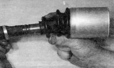
Pic. 3.21b....and a holster complete with a lid
22. Remove the adhesive tape, and then, aligning the marks made during removal, install the tripoid on the axle shaft splines. With hammer and soft metal mandrel (or a suitable piece of pipe with machined ends or a socket) mount the tripod onto the axle shaft, being extra careful not to damage the axle shaft splines or pivot rollers (pic. 3.22).
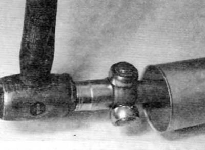
Pic. 3.22. Using a hammer to the end head, put the tripoid on the axle shaft
23. Secure the tripoid with a new circlip, making sure it is correctly positioned in the groove on the axle shaft.
24. Remove adhesive tape and evenly spread the lubricant contained in the repair kit over the tripod and outer element (pic. 3.24). Stuff the case/cover with the rest of the lubricant, and then put the cover on the tripoid. Leave one sachet of lubricant to lubricate the outer element when installing the hinge.
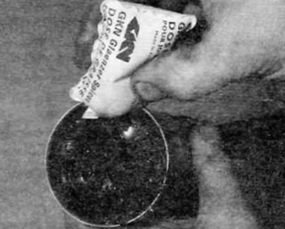
Pic. 3.24. Stuff the hinge and boot/cover with grease
25. Install the new spring, thrust cap and O-ring on the outer pivot member (pic. 3.25, a-c).
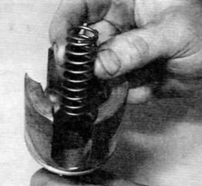
Pic. 3.25 a. Install new spring...
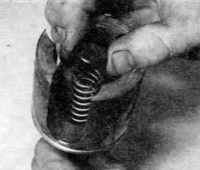
Pic. 3.25b....thrust cap...
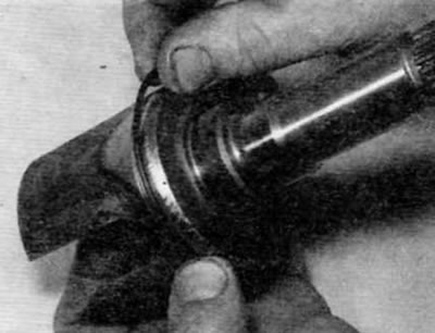
Pic. 3.25, c....and o-ring
26. Install the outer element assembly on the tripoid and bring the thrust cap to the end of the axle shaft. Apply the remainder of the grease to the hinge, and then push the outer element onto the axle shaft, compressing the spring, and install it inside the outer cover. Secure the outer element by tapping the cover evenly on the outer edge of the hinge with a hammer (pic. 3.26. a-c).
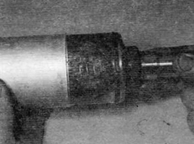
Pic. 3.26 a. Install the outer element on the tripod...
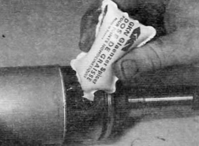
Pic. 3.26b....then squeeze out the rest of the grease...
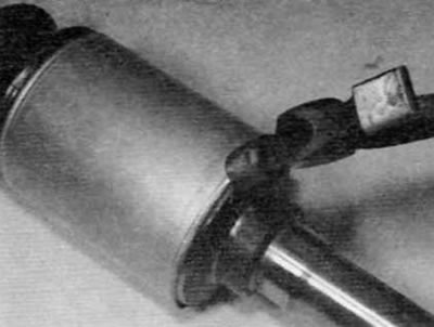
Pic. 3.26, c....and mint the lid around the perimeter
27. Pry up the inside edge of the boot with a blunt tool to equalize the air pressure under the boot. Lock the inner case (pic. 3.27).
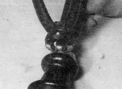
Pic. 3.27. Fastenings of an internal collar of a cover
28. Make sure that the constant velocity joint moves freely in all directions, and then install the axle shaft on the vehicle, as described in paragraph 2.
